Chapter 4: Connecting Environmental Sensors (Optional)
Control and Communication Gateway Installation Guide - MAN-01-00132-1.2
24
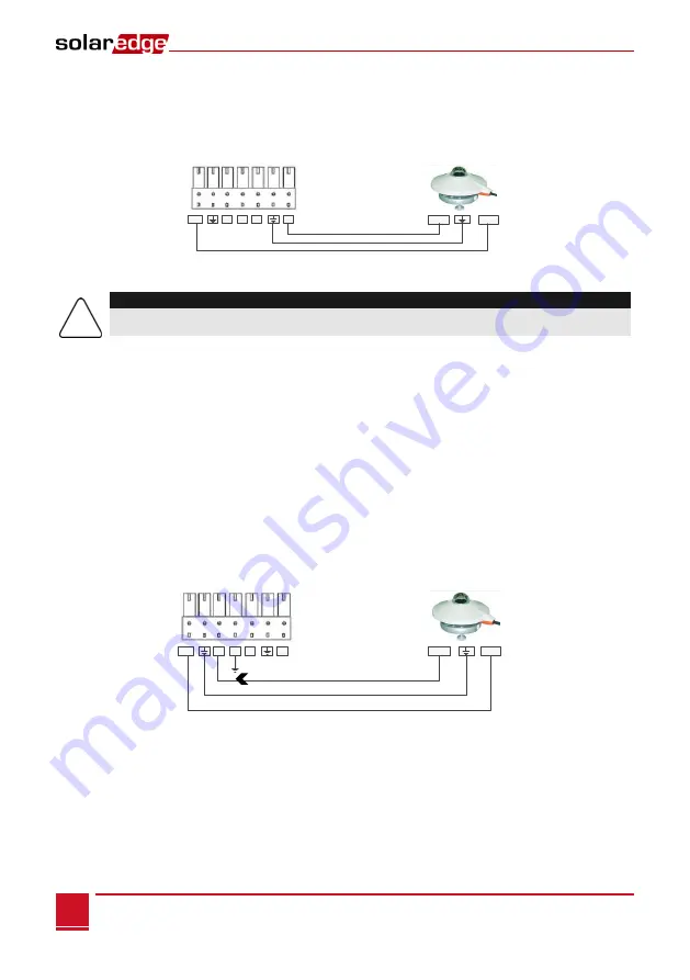
The 12V (pin7) can be used as the supply voltage to the sensor. Optionally, an external power supply
can be connected to the sensors if a different input voltage to the sensor is required.
For an example of sensor connection, refer to
Sensor with
Voltage Output
SolarEdge Gateway
Sensor Interface
Vout Vin
12V I+ I- V2 V1
Figure 15: Voltage sensor connection
CAUTION!
Excessive voltage on the sensor input can damage the SolarEdge gateway. Refer to input ranges
specified in
Appendix A: Technical Specifications
►
To connect a current sensor:
Use a 3-wire cable for this connection. Recommended wire size is 0.52 mm
2
/20 AWG with maximum
length of 50m/164 ft.
1
Connect a current source sensor to either I+ or I-, depending on its operating range:
For positive current:
I+ (pin 5) - connect to the current output (Iout) of the sensor
I- (pin 4) - connect to ground.
GND (pin 6) - connect to the ground connection terminal of the sensor
The 12V (pin7) can be used as the supply voltage to the sensor. Optionally, an external power
supply can be connected to the sensors if a different input voltage to the sensor is required.
Sensor with
Current Output
SolarEdge Gateway
Sensor Interface
Iout Vin
12V I+ I- V2 V1
Figure 16: Current sensor (4-20mA) positive connection
For negative current:
I - (pin 4) - connect to the current output (Iout) of the sensor
I+ (pin 5) - connect to ground.
GND (pin 6) - connect to the ground connection terminal of the sensor
7 6 5 4 3 2 1
7 6 5 4 3 2 1


