Chapter 3: Installation of the inverter
SolarEdge Installation Guide - MAN-01-00060-2.6
16
Chapter 3: Installation of the inverter
Install the inverter either before or after the installation of modules and power optimizers.
WARNING :
Leave at any time the connectors at the base of the inverter rest on the ground, as this may damage them. Let rest the inverter on the floor,
place it on the back, front or side.
Package contents of the inverter
•
SolarEdge inverter
•
A mounting bracket
•
Two Allen screws to the inverter to the mounting bracket
•
This installation guide
•
The Quick Installation Guide
•
The activation of the inverter instructions (can include an activation card)
Identifying the Inverter
Refer to the sticker on the UPS indicating its
Serial number
and his
Electrical Specifications.
Report serial number
Refer to the sticker on the UPS indicating its
Serial number
and his
Electrical Specifications.
Report serial number
Refer to the sticker on the UPS indicating its
Serial number
and his
Electrical Specifications.
Report serial number
Refer to the sticker on the UPS indicating its
Serial number
and his
Electrical Specifications.
Report serial number
Refer to the sticker on the UPS indicating its
Serial number
and his
Electrical Specifications.
Report serial number
when you contact SolarEdge support. The serial number is also required when opening a new site in the SolarEdge
Monitoring Portal. In the following sections, unless otherwise indicated, instructions apply to the inverters both single and
three phase, although only one graphic example is presented.
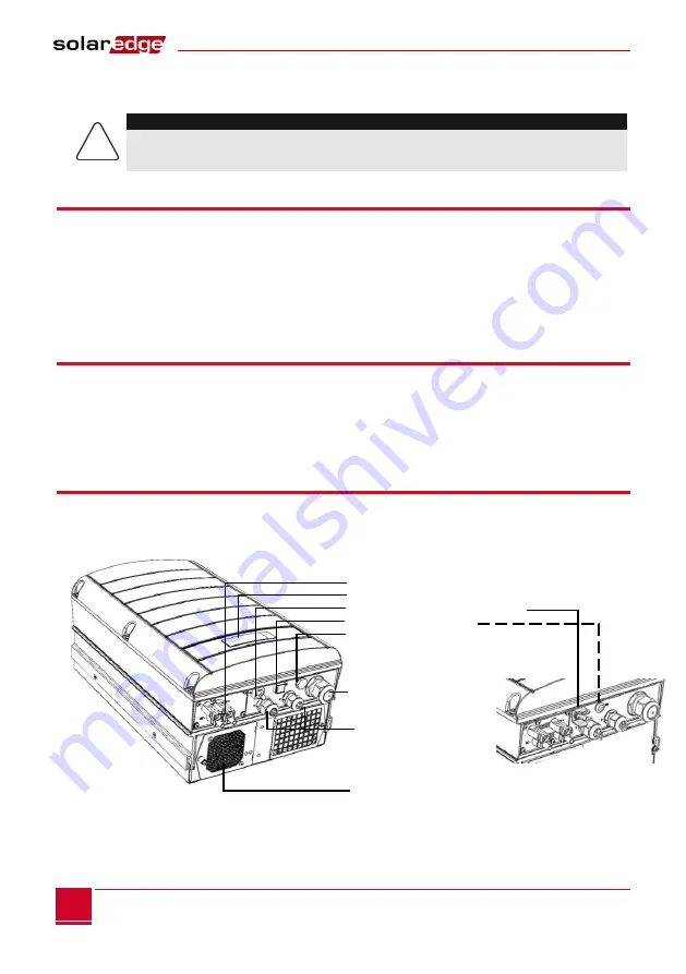
The interfaces of the inverter
The following figure shows the connectors and the components of the inverter, at the base of the inverter. The ON / OFF
switch and the LCD indicator light may vary depending on the inverter model:
Figure 3: Connectors of the inverter (three-phase example)
DC Input Panel LCD and LED ON / OFF switch
Indicator light LCD sealed sheet
IT
Gland communication
Fan


