8 Electrical connection
8 Electrical connection
DANGER
-
There is a risk of fatal electric
shocks when working on electrical
components of the system
–
Work may be performed only by a qualified
electrician.
–
Applicable standards and regulations must
be observed.
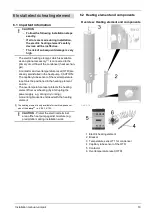
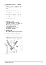
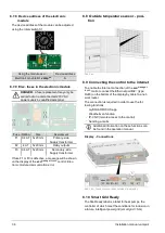
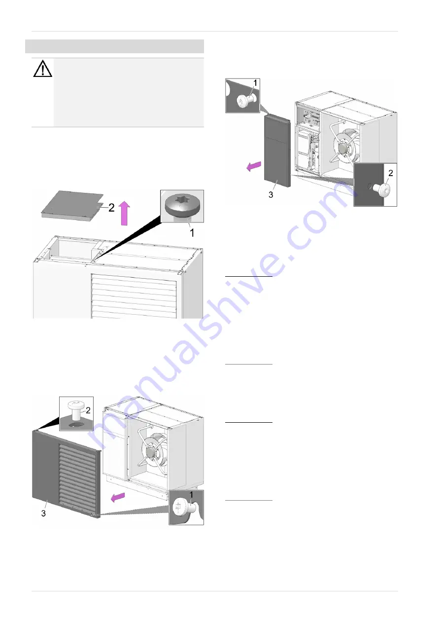
8.1 Access to terminal area
vamp
air
K 08, K 10
►
Loosen 10 pcs. sheet metal screws
1
, remove
cover
2
.
Abb. 2-36: Access to terminal area K 08, K 10
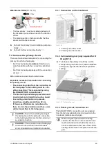
vamp
air
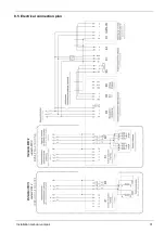
K 12, K 15
►
Loosen 5 pcs. sheet metal screws
1
on under-
side.
►
Loosen 2 pcs. sheet metal screws
2
on both sus-
pensions.
►
Lift cover
3
and remove.
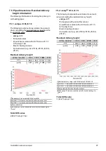
Abb. 2-37
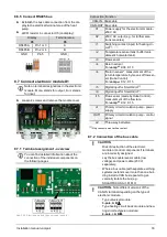
►
Loosen 2 pcs. screws
1
on top side.
►
Loosen 2 pcs. screws
2
each on left and right
side of cover
3
.
►
Remove cover
3
.
Abb. 2-38: Access to terminal area K 12, K 15
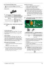
8.2 Terminal assignment
X1 - Heat pump power supply
K 08.3, K 10.3: Three-phase version (= standard)
–
400 V, 5.5 kW, rated current 8 A, terminals
3/N/PE
–
Recommended fuse B13 A
–
Install all-current sensitive type B RCCB.
–
The rotating field does not need to be considered.
–
≥2.5 mm² up to 20 m cable length, 4 mm² with
cable length over 20 m (use flexible cable).
K 08.1, K 10.1: Single-phase design
–
230 V, 5.5 kW, maximum operating current 20 A
–
Recommended fuse B25 A
–
≥4 mm² up to 20 m cable length, 6 mm² with cable
length over 20 m (use flexible cable).
K 12.3, K 15.3: Three-phase version (= standard)
–
400 V, 8 kW, rated current 12 A, terminals 3/N/PE
–
Recommended fuse B16 A
–
Install all-current sensitive type B RCCB.
–
The rotating field does not need to be considered.
–
≥2.5 mm² up to 20 m cable length, 4 mm² with
cable length over 20 m (use flexible cable).
K 12.1, K 15.1: Single-phase design
–
230 V, 8 kW, maximum operating current 20 A
–
Recommended fuse B35 A
–
≥4 mm² up to 20 m cable length, 6 mm² with cable
length over 20 m (use flexible cable).
28
Installation manual
vampair

