12
Safety, Installation, and Operations Manual
©2021 The Solaria Corporation All rights reserved. Contents subject to change without notice. AUS-MAN-0002 Rev 01, 03-2021
Power Unlocked by Design
Correction factor for the open-circuit voltage can be calculated based on the following formula: CVoc=1-
βVoc×(25-T). T is the lowest expected ambient temperature at the system location. β(%/°C) is the temperature
coefficient of the selected module Voc (refer to corresponding datasheet).
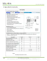
An appropriately rated over-current protection device must be used when the reverse current could exceed the value
of the maximum fuse rating of the Modules (20A). An over-current protection device is required for each series
string if more than two series strings are connected in parallel, as illustrated in Figure 5.
6.2 Cables & Wiring
The Module junction boxes have been designed to be easily interconnected in series for their well-connected cable
and the connector with IP67 protection grade. Each Module has two single-conductor wires, one positive and one
negative, which are pre-wired inside the junction box. The connectors at the opposite end of these wires allow easy
series connection of adjacent Modules by firmly inserting the positive connector of a Module into the negative
connector of an adjacent Module until the connector is fully seated.
Use field wiring with suitable cross-sectional areas that are approved for use at the maximum short-circuit current
of the Modules. Solaria recommends installers use only sunlight resistant cables qualified for direct current (DC)
wiring in PV systems. The minimum wire size should be 4mm2(12AWG).
Rating Required Minimum Field Wiring
Cables should be fixed to the mounting structure in such a way that mechanical damage of the cable and/or the
Modules is avoided. Do not apply stress to the cables. The minimum cables bending radius should be 38.4mm. Any
cable damage caused by bending too much or cable management system is not covered under Solaria’s warranty.
For fixing, use appropriate means, such as sunlight resistant cable ties and/or wire management clips specifically
designed to attach to the Module frame. While the cables are sunlight resistant and waterproof, where possible,
avoid direct sunlight exposure and water immersion of the cables.
Cable arrangement must comply with local laws and regulations.
6.3 Connectors
Keep connectors dry and clean, and ensure that connector caps are hand tight before connecting the Modules.
Do not attempt making an electrical connection with wet, soiled, or otherwise faulty connectors. Avoid sunlight
exposure and water immersion of the connectors. Avoid connectors resting on the ground or roof surface.
Faulty connections can result in arcs and electrical shock. Check that all electrical connections are securely
fastened. Make sure that all locking connectors are fully engaged and locked. Connector interconnect must reach
the corresponding IP protection level, so as to achieve the electrical security. It is not recommended to interconnect
different types of connectors.
Testing Standard
Wire Size
Temperature Rating
EN 50618:2014
4mm2
-40ºC to +90ºC
Testing Standard
Manufacture
Type
Rating
Temperature Rating
IEC 61852:2014
Stäubli Electrical
Connectors AG
https://ec.staubli.com/
PV-KST4-EV02/6II-UR
PV-KBT4-EV02/6II-UR
1500VDC;
45A (1x4mm
2
cable)
-40ºC to +85ºCvv

