background image

5

Safety, Installation, and Operations Manual

©2021 The Solaria Corporation     All rights reserved.   Contents subject to change without notice.     AUS-MAN-0002 Rev 01, 03-2021

Power Unlocked by Design

3.1 Product Identification

Each Module has a label providing the following information:

1. Nameplate: describes the product type; Peak power, Max. power current, Max. power voltage, open circuit 

voltage, short circuit current, all as measured under standard test conditions; Certifications mark, the 

maximum system voltage etc.

2. Serial number: each individual module has a unique serial number. The serial number has 16 digits. The 1

st


and the 2

nd

 digits are the year code, and the 3

rd

 is the month code (A, B, C stands for October, November and 

December respectively). For example, 121 XX XX XX XXXXXXX means the module was assembled and tested 

in January of 2012. 

3.2 Conventional Safety

Solaria Modules are designed to meet the requirements of IEC 61215 and IEC 61730, application class II. Modules 

rated for use in this application class may be used in system operating at greater than 50V  DC or 240W, where 

general contact access is anticipated. Modules qualified for safety through IEC 61730-1 and IEC 61730-2 and within 

this application class are considered to meet the requirements for safety class II equipment.

When Modules are mounted on rooftops, the roof must have a fire resistant covering suitable for this application. 

Rooftop PV systems should only be installed on rooftops capable of handling the additional weighted load of PV 

system components, including Modules, and have a complete analysis of the structure performed by a certified 

building specialist or engineer. 

For your safety, do not attempt to work on a rooftop until safety precautions have been identified and taken, 

including without limitation: fall protection measures, ladders or stairways, and personal protective equipment.
For your safety, do not install or handle Modules under adverse conditions, including without limitation strong or 

gusty winds, and wet or frosted roof surfaces.

3.3 Electrical Performance Safety

Photovoltaic Modules can produce DC electricity when exposed to light and therefore can produce an electrical 

shock or burn. DC voltages of 30 Volts or higher is potentially lethal.
 Modules produce voltage even when not connected to an electrical circuit or load. Please use insulated tools and 

electrically insulated gloves when working with Modules in sunlight.
Modules have no on/off switch. Modules can be rendered inoperative only by removing them from sunlight, or by 

fully covering their front surface with cloth, cardboard, or other completely opaque material, or by working with 

Modules face down on a smooth, flat surface. 

In order to avoid arcs and electrical shock, please do not disconnect electrical connections under load. Faulty 

connections can also result in arcs and electrical shock. So please keep connectors dry and clean, and ensure that 

they are in proper working condition. Never insert metal objects into the connector, or modify them in any way in 

order to secure an electrical connection.
Also in order to avoid the sand or water vapor entering which may cause a safety issue with the connection, the 

modules need to be installed and connected to the combiner box once they are taken out from the carton box, 

keep the connectors dry and clean during the installation, if the modules are not be installed within a week, rubber 

Summary of Contents for PowerXT-395R-PM

Page 1: ...ions Manual 2021 The Solaria Corporation All rights reserved Contents subject to change without notice AUS MAN 0002 Rev 01 03 2021 SAFETY INSTALLATION AND OPERATIONS MANUAL Australia PowerXT 400 PM R Module Power Unlocked by Design ...

Page 2: ... documentation is updated frequently Check the Solaria website solaria com australia for the latest information For warranty text refer to solaria com australia docsAU For Solaria patent information refer to solaria com patents 2021 The Solaria Corporation All rights reserved Registered Office Solaria Australia Pty Ltd C o Mertons Corporate Services Pty Ltd Level 7 330 Collins Street Melbourne Vic...

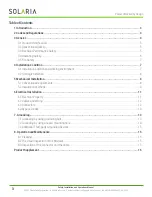
Page 3: ...Condition 7 4 1 Installation position and working environment 7 4 2 Tilt Angle Selection 8 5 Mechanical Installation 8 5 1 Conventional requirements 8 5 2 Installation methods 9 6 Electrical Installation 11 6 1 Electrical Property 11 6 2 Cables and Wiring 12 6 3 Connectors 12 6 4 Bypass Diodes 13 7 Grounding 13 7 1 Grounding by using grounding bolt 13 7 2 Grounding by using unused mounting hole 14...

Page 4: ...tents or other rights of third parties that may result from use of Modules Solaria reserves the right to make changes to the product specifications or installation manual without prior notice Failure to comply with the requirements listed in this manual will invalidate the Solaria Limited Product Warranty Warranty Additional recommendations are provided to enhance safety practices and performance ...

Page 5: ...rmed by a certified building specialist or engineer For your safety do not attempt to work on a rooftop until safety precautions have been identified and taken including without limitation fall protection measures ladders or stairways and personal protective equipment For your safety do not install or handle Modules under adverse conditions including without limitation strong or gusty winds and we...

Page 6: ...to damage Secure pallets from falling over Do not exceed the maximum height of pallets to be stacked as indicated on the pallet packaging Store pallets in a ventilated rain proof and dry location until the Modules are ready to be unpacked Do not lift the Modules by grasping the Module s junction box or electrical leads in any condition Do not stand or step on the Modules Do not drop the Modules on...

Page 7: ...ules Modules must be mounted on appropriate mounting structures positioned on suitable buildings the ground or other structures suitable for modules e g carports building facades or PV trackers Modules must not be installed in locations where they could be submerged in water The recommended ambient temperature should be within 40 C 40 F to 40 C 104 F The temperature limits are defined as the month...

Page 8: ...be securely attached to the mounting structure In regions with heavy snowfall select the height of the mounting system so that the lowest edge of the Modules is not covered by snow for any length of time In addition ensure that the lowest portion of the Modules is placed high enough so that it is not shaded by plants or trees or damaged by flying sand When the Modules are supported parallel to the...

Page 9: ...unting holes located in the frame s back flanges Refer to what is shown in Figure 2 Mounting Details For your reference please use the components specified below 5 Front side test load 2400Pa backside test load 2400Pa and both safety factor is 1 5 6 Recommended torque is between 14N m to 20N m 5 2 2 Modules Installed With Clamp Modules can be mounted using specialized clamps as shown in Figure 3 A...

Page 10: ...es Avoid shading effects from the Modules clamps Drainage holes on the Module frame must not be closed or obscured by the clamps D Front side test load 2400Pa backside test load 2400Pa and both safety factor is 1 5 Note The module has been qualified following the mechanical load requirements per IEC61215 2016 using 3 cycles with a test load of 2400Pa An additional test cycle of 5400Pa Front 4th cy...

Page 11: ...ed by a factor of 1 25 when determining component voltage ratings conductor capacities fusing sizes and size of controls connected to the Module output Voltages are additive when Modules are connected directly in series and Modules currents are additive when Modules are connected directly in parallel as illustrated in Figure 6 Modules with different electrical characteristics must not be connected...

Page 12: ...n PV systems The minimum wire size should be 4mm2 12AWG Rating Required Minimum Field Wiring Cables should be fixed to the mounting structure in such a way that mechanical damage of the cable and or the Modules is avoided Do not apply stress to the cables The minimum cables bending radius should be 38 4mm Any cable damage caused by bending too much or cable management system is not covered under S...

Page 13: ...lloy and penetrate the surface of the frame oxidation film Please don t drill any additional grounding hole on the frame of the Modules otherwise it will expressly void the Solaria warranty For optimal performance Solaria Solar Modules should only be used in configurations where the DC cathode of the Modules array is connected to ground Failure to comply with this requirement will reduce the perfo...

Page 14: ...the mounting holes in the frame Thread the grounding clamp and the frame with grounding bolt B Put the toothed gasket into the other side then tighten and lock the nut The recommended torque of locking the nut is 2 0 N M 2 2 N M C Thread the grounding clamp with grounding wire The materiel and size of grounding wire should meet the relevant requirements of the national regional and local code law ...

Page 15: ...l homogeneous and the power reduction usually is not obvious When Modules are operational there may exist environmental factors that cast shade dust plants and so on that may distinctly reduce the power output Solaria advises that there should be no obstructed object over the Module s surface at any time The cleaning frequency depends on the frequency of debris or dust accumulation In many instanc...

Page 16: ...trical specifications or additional information The datasheet is available at www solaria com A Performance at STC Module type Pmp W Voc V Vmp V Isc A Imp A PowerXT 395R PM 395 51 45 42 78 9 95 9 23 PowerXT 400R PM 400 51 68 43 08 9 97 9 28 PowerXT 405R PM 405 51 91 43 51 9 98 9 32 PowerXT 410R PM 410 52 04 43 63 10 00 9 41 PowerXT 415R PM 415 52 14 43 93 10 10 9 45 Remark 1 Maximum overcurrent pr...

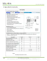
Page 17: ... Installation and Operations Manual 2021 The Solaria Corporation All rights reserved Contents subject to change without notice AUS MAN 0002 Rev 01 03 2021 Power Unlocked by Design B Bypass Diode For Junction Box ...

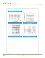
Page 18: ...18 Safety Installation and Operations Manual 2021 The Solaria Corporation All rights reserved Contents subject to change without notice AUS MAN 0002 Rev 01 03 2021 Power Unlocked by Design ...

Page 19: ...Contents subject to change without notice AUS MAN 0002 Rev 01 03 2021 Power Unlocked by Design Solaria Australia Pty Ltd C o Mertons Corporate Services Pty Ltd Level 7 330 Collins Street Melbourne Victoria 3000 Australia Australia Contact Bob Blakiston T 61 417 948 319 www solaria com australia ...

Reviews: