background image


19

WiFi Kit Quick Guide


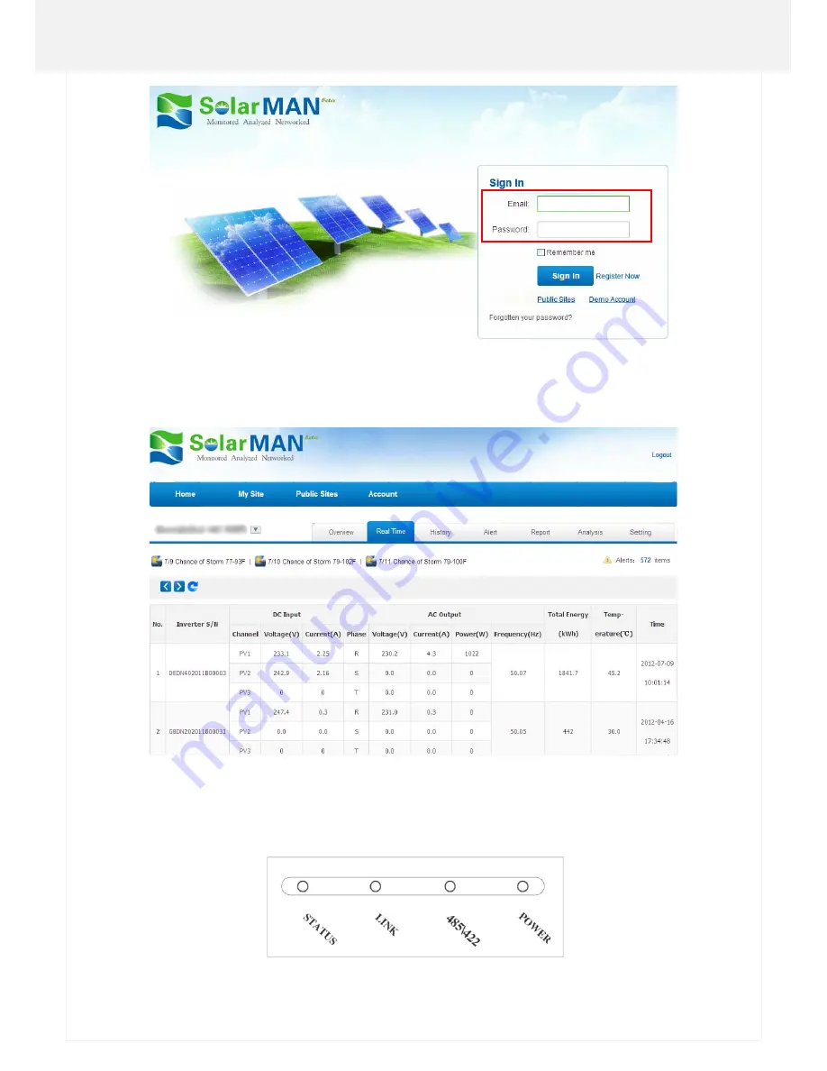
Notices:Ifusersaccessthemonitoringsystemforthefirsttimewithintenminutesaftersuccessfulregistration,please
checkthe"RealTime"interfaceasshownbelow.IftherearedatashownintheRealTimeinterface,networksettingof
dataloggerandotherconnectionaredeemedsuccessful.


G:Debug


I. LED indication 

Summary of Contents for S-WE01S

Page 1: ...WiFi Kit S WE01S Quick Guide WiFi Kit S WE01S is an external data logger in the SolarMAN PV monitoring series ...

Page 2: ...ver realizing remote monitoring for users In addition Ethernet is also available for connection to router enabling transmission of data Users can check the runtime status of the device by checking the 4LEDs on the panel indicating Power 485 422 Link and Status respectively A Unpack B Install data logger C Connect data logger and inverters D Network setting E Register on SolarMAN Portal F Log in So...

Page 3: ...ms please refer to corresponding chapters of S WE01S User Manual for details A Unpack I Checklist After unpacking the box please make sure all the items are contained as follows 1 PV data logger WiFi Kit S WE01S 1 power adapter with European or British plug 2 screws 2 expandable rubber hoses 1 Quick Guide II Interface and connection ...

Page 4: ... corresponding relationship between inverter and GPRS Wifi unit B Install data logger WiFi Kit can be either wall mounted or flatwise Please refer to 3 Installation of User Manual for details C Connect data logger and inverters ...

Page 5: ...ta logger with network cable and connect data logger and power supply with power adapter II Connection with multiple inverters 1 String connect multiple inverters with network cables 2 Connect the first or last inverter in the string to data logger with network cable 3 Connect data logger to power supply with power adapter Notice The connectors of the connection cable may differ according to the b...

Page 6: ...rs may choose the appropriate method accordingly I Connection via WiFi Notice The setting hereinafter is operated with Window XP for reference only If other operating systems are used please follow the corresponding procedures 1 Prepare a computer or device with WiFi 2 Check the mode of WiFi a When STATUS is flashing which means that the WiFi module is in AP mode users can proceed to step 4 for ne...

Page 7: ...6 WiFi Kit Quick Guide 2 Select Obtain an IP address automatically and click OK ...

Page 8: ...ng module no passwords required as default The network name consists of AP and the serial number of the product Then click Connect 3 Connection successful Notice If AP_ serial number of product is not available in the wireless network list there may be problems in the connection or setting of data logging module Please refer to 5 Debug of User Manual for troubleshooting ...

Page 9: ...e and password both of which are admin as default Recommended browsers Internet Explorer 8 Google Chrome 15 Firefox 10 b In the configuration interface of WiFi module you can view general information of the module Follow the setup wizard to start quick setting 1 Click Wizard to start 2 Click Start to continue admin admin ...

Page 10: ...9 WiFi Kit Quick Guide 3 Select Wireless connection and click Next 4 Click Refresh to search available wireless networks or add it manually ...

Page 11: ...to connect then click Next Notice If the signal strength RSSI of the selected network is 10 which means unstable connection please adjust the antenna of the router or use a repeater to enhance the signal 6 Enter the password for the selected network then click Next ...

Page 12: ...11 WiFi Kit Quick Guide 7 Select Enable to obtain an IP address automatically then click Next 8 If setting is successful the above page will display Click OK to restart ...

Page 13: ...12 WiFi Kit Quick Guide 9 If restart is successful the above page will display II Connection via Ethernet 1 Connect computer and data logger via Ethernet port with network cable 2 Reset the data logger ...

Page 14: ... by the router Open a web browser and enter the assigned IP address to get access to the configuration interface of the data logger Fill in username and password both of which are admin as default Recommended browsers Internet Explorer 8 Google Chrome 15 Firefox 10 4 Set network to the module In the configuration interface of data logger you can view general information of the device Follow the se...

Page 15: ...14 WiFi Kit Quick Guide 3 Select Cable Connection and you can choose to enable or disable the wireless function then click Next 4 Select to obtain an IP address automatically t Enable hen click Next ...

Page 16: ...15 WiFi Kit Quick Guide 5 If setting is successful the following page will display Click OK to restart 6 If restart is successful the following page will display ...

Page 17: ... 2 5 minutes the connection is successful If STATUS is flashing which means unsuccessful connection please repeat the setting from step 3 E Register on SolarMAN Portal Open a web browser and visit the portal website http www solarmanpv com portal Supported browsers Internet Explorer 8 Google Chrome 10 Firefox 9 Safari 4 1 Click Register Now ...

Page 18: ...17 WiFi Kit Quick Guide 2 Fill in your email address and password then click Next 3 Fill in the information as required then click Complete ...

Page 19: ...eturn to the homepage of the portal F Log in SolarMAN Portal to manage power station After successful registration and account activation open the login page of SolarMAN Portal and input the correct E mail and password to access the monitoring system and start monitoring and management of power plants ...

Page 20: ... for the first time within ten minutes after successful registration please check the Real Time interface as shown below If there are data shown in the Real Time interface network setting of data logger and other connection are deemed successful G Debug I LED indication ...

Page 21: ... Flashing LINK Flashing Data is transmitting via port LINK On WiFi in AP mode a terminal connected LINK Off WiFi in AP mode no terminal connected II Trouble shootings Phenomenon Meaning Solutions POWER 485 422 LINK STATUS Off Off Off Off No power supply Connect power supply and ensure good contacts On Off X X Connection with inverter is abnormal Check the connection cable and ensure that the cable...

Page 22: ...en screw or adjust the antenna please note that only the metal part can be touched and do not screw the plastic part otherwise the antenna may be damaged Note 3 If the equipment still fails to work upon above solutions please contact your device customer service H Contact If any technical problems please contact us with the following information in hand Device model Serial number of data logger Nu...

Reviews: