17
en
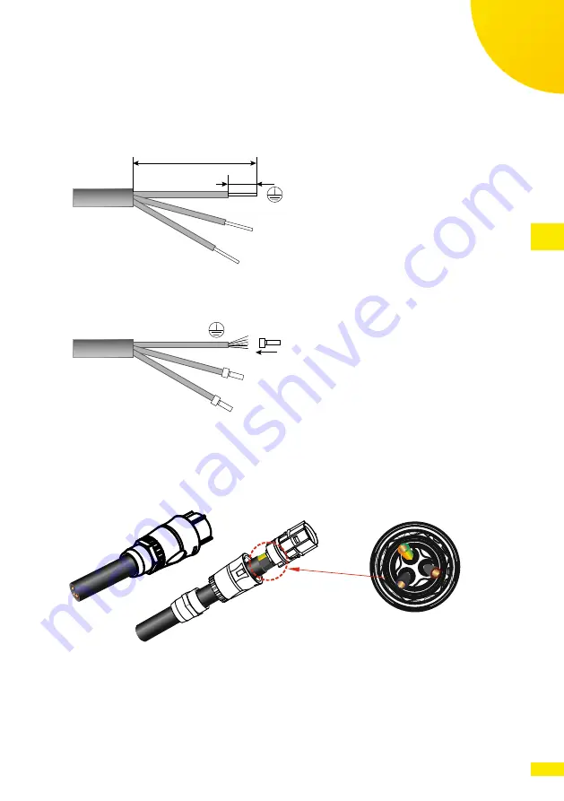
1. Remove the external isolation of the cable to free the N (Neutral) and L
(Line) wires for a length Y of 36 mm, and to free the PE (Protective Earth)
wire for a length Y of 40 mm. Remove the isolation of the individual wires
for a length X of about 10 ... 15 mm.
y
x
N
L
Fig. 9: Removing the isolation of the AC cable
2. Crimp or solder tip terminals on the wires.
N
L
Fig. 10: Connecting the tip terminals to the AC cable
3. Check that all the parts of the AC connector are present and in good condi-
tion. Insert the cable in the cable gland and into the connector enclosure.
4. Insert and lock the individual conductors PE, N and L in the respective con-
nector terminals.
G
N
L
Zoom in
Fig. 11: Connecting the AC cable to the AC connector
5. Insert the connector in the enclosure and pull the cable backwards until
the tabs on the sides click in position.
6. Tighten the cable gland with a 4Nm torque.
7. Insert the connector in the counterpart located at the bottom of the
inverter pushing it until the side tab clicks and locks it in position.

