39
en
5�12
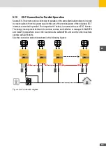
ES-T Connection for Parallel Operation
Several ES-T inverters can be connected in parallel on the same distribution network in order
to create a plant of nominal power equal to the sum of the nominal power of the individual ES-T
inverters connected in parallel. The respective HV battery is connected to each ES-T inverter.
The energy management between the various devices and batteries is managed in MASTER
and SLAVE mode where one of the inverters acts as MASTER unit and the other inverters
operate as SLAVE units.
See the connection instructions shown in the following figures:
CAN
CAN
CAN
CAN
INV_1
(MASTER)
INV_2
(SLAVE)
INV_3
(SLAVE)
INV_10
(SLAVE)
METER
AC GRID
AC GRID
AC GRID
AC GRID
Fig. 23: ES-T connection diagram
Summary of Contents for 10ES-T
Page 1: ...Instruction Manual SolarMax ES T series 5ES T 6ES T 8ES T 10ES T ...
Page 10: ...10 3 2 Function Fig 2 Function of ES T ...
Page 22: ...22 5 2 Electrical connection diagram ES T Fig 6 Electrical connection diagram ...
Page 74: ...74 Fig 52 Login page The HOME page will appear Fig 53 HOME page ...


