43
en
7 Control Panel
7�1
General Information
1
2
3
4
5
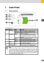
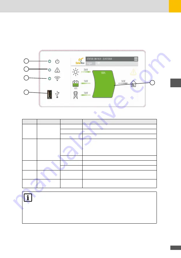
Fig. 26: Display of ES-T
Position Function
State
Description
1
Power Supply
LED on
The ES-T is powered and is operating regularly.
LED blinking
The ES-T is in the start-up and self-test phase..
LED off
The ES-T is not powered.
2
General alarm
LED on
The ES-T has detected a fault. The LCD display
activates the corresponding alarm icon and shows
the information related to the alarm occurred on the
status bar
LED of
The ES-T has not detected any fault.
3
Communication LED on
Communication with external devices is enabled.
LED of
Communication with external devices is disabled.
4
USB port
ES-T on
USB port available for data download, firmware
update, WiFi dongle connection.
5
Graphic touch-
screen display
ES-T on
Graphic touch screen graphic display which displays
the system status and user / installer settings.
NOTE
Do not connect portable hard disks, MP3 players, computers and any other device
other than a flash USB memory or WiFi dongle to the USB port. The system is com-
patible with most of the flash USB memories on the market. However, the system
may not recognize some types of USB memory, in this case it is recommended to
try again replacing it with another model.
Summary of Contents for 10ES-T
Page 1: ...Instruction Manual SolarMax ES T series 5ES T 6ES T 8ES T 10ES T ...
Page 10: ...10 3 2 Function Fig 2 Function of ES T ...
Page 22: ...22 5 2 Electrical connection diagram ES T Fig 6 Electrical connection diagram ...
Page 74: ...74 Fig 52 Login page The HOME page will appear Fig 53 HOME page ...

