44
7�2
“HOME” Page
5
6
7
9
8
4
3
10
1
2
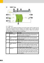
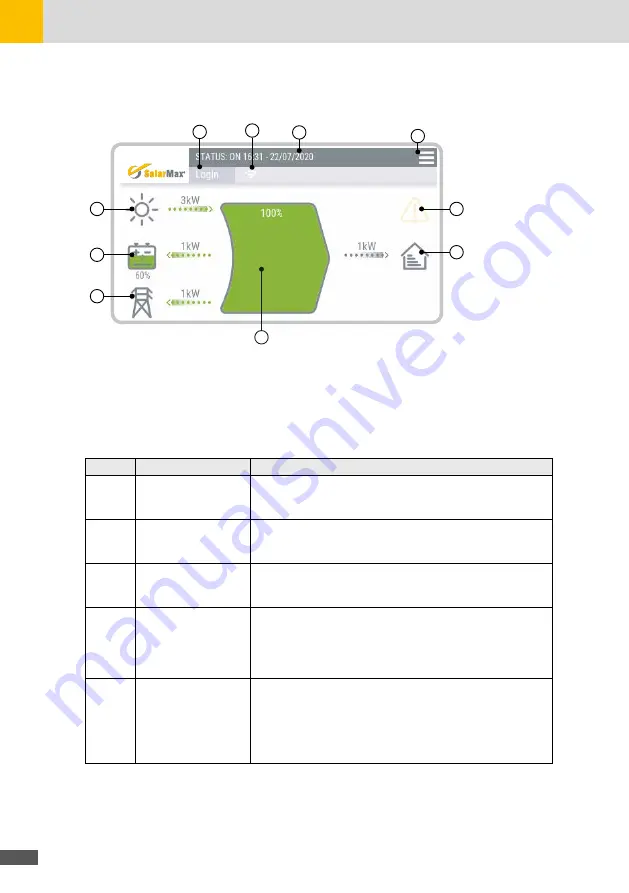
Fig. 27: HOME Screen
The “HOME” screen displays and analyses in real time all parts of the ES-T system. All the
power sources supplied to meet the demands of the domestic needs and their operating
parameters are constantly monitored and displayed in real time. Similarly, the central indi-
cator will display in real time the system energy balance.
Position Function
Description
1
System status bar
The system indicator bar shows the ES-T operating status, the
current date and time. If faults are detected, the alarm codes
detected by the system are displayed
2
Access to the “MENU”
page
This key allows the operator to access the built in datalogger
(graphics, data and statistical data), system configuration and
programming menus.
3
Access to the “LOGIN” This key allows the operator to view the login page to access the
different programming level of the system by entering the access
password.
4
“ENERGY BALANCE”
icon
This dynamic icon shows the system energy balance in real time:
the green colour shows the percentage of energy produced by
renewable sources (PV and batteries), the purple colour shows
the energy drawn from the grid in order to meet the demands of
the residential system connected to the ES-T.
5
“SUN” icon
The “SUN icon shows if a PV solar system is connected to the
system. The flow of energy coming from that source is displayed
on the bar located next to the icon. The numbers shown above
the bar, which can be scrolled by simply pressing the bar itself,
display in real time the voltage, current and power values related
to the PV generator.
Summary of Contents for 10ES-T
Page 1: ...Instruction Manual SolarMax ES T series 5ES T 6ES T 8ES T 10ES T ...
Page 10: ...10 3 2 Function Fig 2 Function of ES T ...
Page 22: ...22 5 2 Electrical connection diagram ES T Fig 6 Electrical connection diagram ...
Page 74: ...74 Fig 52 Login page The HOME page will appear Fig 53 HOME page ...

