17
en
Additional Protective Devices
The ES-T system is fitted with additional protective devices to ensure safe operation in various
operating conditions:
■
Active temperature control and automatic power derating in case of abnormal operating
conditions or outside the limits allowed in order to prevent the system from overheating.
■
PV polarity reversal protections.
■
Battery polarity reversal protection.
■
PV, BAT, AC GRID, EPS input/output overvoltage protection.
■
AC GRID, EPS short-circuit protection.
3�3
Touch Screen Control Panel
The control panel fitted on the ES-T is a graphic touchscreen display. To input commands,
simply touch the surface of the display with a finger or with objects suitable for the purpose.
Metallic or excessively sharp materials must not be used.
The display backlighting is turned off when the display is not used by the user. The LCD dis-
play remains operational even if it appears to be off. To reactivate it, simply touch the display
surface.
4 Installation
NOTE
The installation must be carried out only by experienced staff, authorized by the
manufacturer.
4�1
Lifting and Transport instructions
Transport and Handling
Transport of the equipment, especially on the road, must be carried out with means able
to protect the system components (especially electronic components) from major impacts,
humidity, vibrations, etc. During handling, sudden or fast movements which could create dan-
gerously sway the system must be avoided.
Lifting
The manufacturer normally packs and protects each component by using devices able
to ease its transport and handling operations but, gene-rally speaking, these opera-
tions must be carried out by staff specialized in loading and unloading components.
The ropes and vehicles used for lifting must be suitable for with standing the weight of the equipment.
Do not lift multiple units or parts of the equipment at the same time, unless otherwise stated.
The ES-T is not equipped with specific lifting means.
Summary of Contents for 10ES-T
Page 1: ...Instruction Manual SolarMax ES T series 5ES T 6ES T 8ES T 10ES T ...
Page 10: ...10 3 2 Function Fig 2 Function of ES T ...
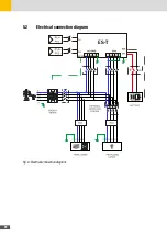
Page 22: ...22 5 2 Electrical connection diagram ES T Fig 6 Electrical connection diagram ...
Page 74: ...74 Fig 52 Login page The HOME page will appear Fig 53 HOME page ...

