19
en
10 cm
50 cm
+40°C
21 kg
-10°C
50 cm
50 cm
25 Kg
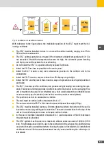
Fig. 3: Conditions for installation location
With reference to the figure above, the installation position of the ES-T must meet the fol-
lowing conditions:
■
The ES-T must be installed indoors in a room with relative humidity ranging from 5% to
95% without condensation.
■
The ES-T optimal operation is ensured if the maximum ambient temperature of 40°C is
not exceeded. Should the temperature become too high, the automatic power derating
will trip to prevent the system from overheating.
■
Do not install the ES-T in a position directly exposed to the sun.
■
Install the ES-T as close as possible to the meter panel.
■
Install the ES-T in such a way as to ensure easy access to the controls and to the
connections
■
Install the ES-T in such a way as to have the LCD display at eye height.
■
Install the ES-T and the power lines in such a way as to prevent access to pets (rodents in
particular).
■
The ES-T, in some specific conditions, can produce a slight buzzing noise during its oper-
ation. This noise is normal and does not affect its performance, but can be annoying if the
unit is mounted onto a wall of an inhabited area, onto a wall adjacent to an inhabited area
or onto certain type of materials (such as thin wooden panels or metal plates).
■
The position must not be accessible to children.
■
The wall must be vertical, with a maximum tilt of ± 5°.
■
The surface where the ES-T will be installed must withstand its weight (25 kg).
■
The ES-T must be installed leaving a 500mm clearance where the bottom of the unit is
located to ensure easy cabling and connection. There are no restrictions for the top of the
unit as the ventilation system does not require vertical outlets.
■
In the case of multiple installation of several ES-T, a side clearance of 500 mm between
the units must be provided.
■
The ES-T system must be used at a maximum altitude above sea level of 3000m (9750
feet). For altitudes above 2000m, due to the rarefaction of the air, specific conditions may
occur which must be considered when choosing the place of installation. All installations
at altitudes above 2000m must be assessed case by case considering the following crit-
ical issues:
Summary of Contents for 10ES-T
Page 1: ...Instruction Manual SolarMax ES T series 5ES T 6ES T 8ES T 10ES T ...
Page 10: ...10 3 2 Function Fig 2 Function of ES T ...
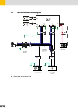
Page 22: ...22 5 2 Electrical connection diagram ES T Fig 6 Electrical connection diagram ...
Page 74: ...74 Fig 52 Login page The HOME page will appear Fig 53 HOME page ...

