23
en
5�3
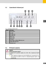
Connections in the lower part
7
6
8
9
10
5
4
3
2
1
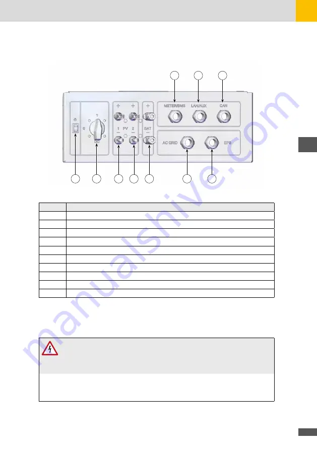
Fig. 7: Connections in the lower part
Position
Description
1
ON/OFF switch
2
DC switch
3
PV1 string input
4
PV2 string input
5
Battery input
6
AC grid output
7
EPS output
8
Energy meter and battery BMS wiring input
9
LAN and AUX wiring input
10
CAN wiring input
5�4
PV Panels Connection
DANGER!
Fatal electric shock hazard!
In daylight the PV generator supplies the inverter with a dangerously high DC
voltage.
■
The PV generator voltages are very high. NEVER plug or unplug the DC con-
nectors when the inverter is turned on, otherwise dangerous electric arcs
could develop.
Summary of Contents for 10ES-T
Page 1: ...Instruction Manual SolarMax ES T series 5ES T 6ES T 8ES T 10ES T ...
Page 10: ...10 3 2 Function Fig 2 Function of ES T ...
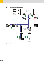
Page 22: ...22 5 2 Electrical connection diagram ES T Fig 6 Electrical connection diagram ...
Page 74: ...74 Fig 52 Login page The HOME page will appear Fig 53 HOME page ...

