24
10 min
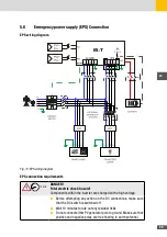
DANGER!
Fatal electric shock hazard!
Components within the inverter are charged with a high voltage.
■
Before attempting any action on the DC connections, make sure
that the DC switch is switched off
■
Wait 10 minutes to rule out any residual risks
■
Do not connect either PV generator pole to ground. Make sure that
positive and negative poles are free floating to earth potential.
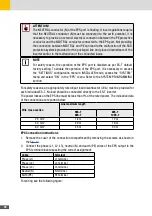
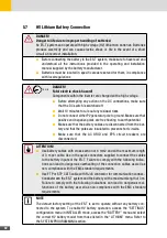
ATTENTION!
The voltage applied to each input channel of the ES-T, determined at the minimum
rated temperature for operation, must NEVER exceed 1000V. Exceeding the limit
can cause serious damage to the ES-T.
5�4�1 Reduction of Electromagnetic Disturbances
NOTE
The ES-T may be not compliant with the EMC standards requirements if the ferrite
cores are not installed according to the instructions provided.
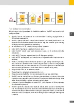
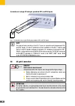
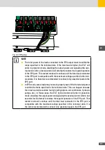
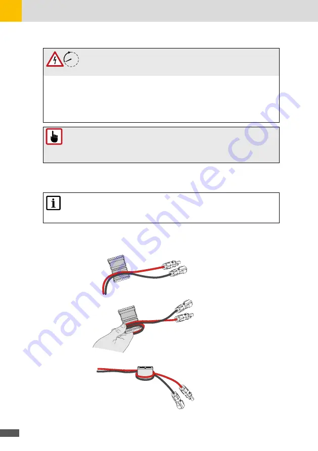
In order to minimize electromagnetic disturbances, it is required to install the EMI Suppression
Clip Ferrite Cores supplied in the box on the cables connected to the PV1 and PV2 inputs.
See the following figure for installation instructions:
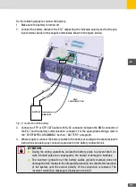
Fig. 8: Supression Ferrite Cores Installation for PV cables
Summary of Contents for 10ES-T
Page 1: ...Instruction Manual SolarMax ES T series 5ES T 6ES T 8ES T 10ES T ...
Page 10: ...10 3 2 Function Fig 2 Function of ES T ...
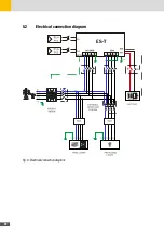
Page 22: ...22 5 2 Electrical connection diagram ES T Fig 6 Electrical connection diagram ...
Page 74: ...74 Fig 52 Login page The HOME page will appear Fig 53 HOME page ...


