28
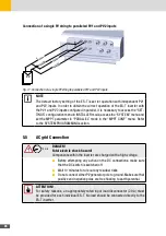
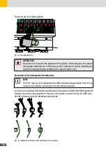
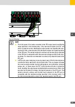
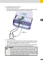
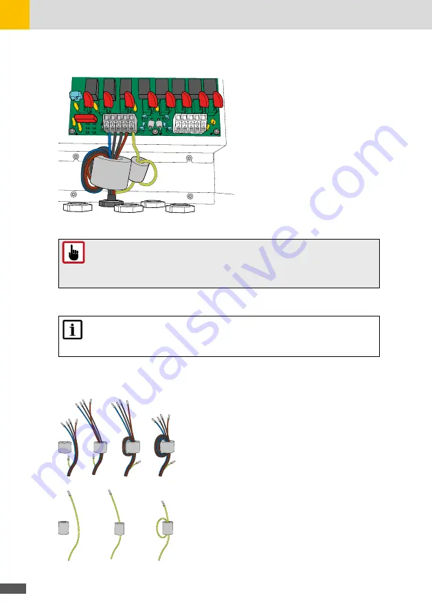
For wiring see the following figure:
M10
EPS
GRID
C150
C146
C144
C156
M6
M7
C162
C163
TZ14
TZ13
C152
C145
C153
C151
Fig. 13: AC output wiring
ATTENTION!
Be careful not to reverse the phases with the neutral. If this happens, the system
may present malfunctions. In this case, the ES-T detects the fault by disabling the
operation and signaling the problem with a specific alarm code.
Reduction of Electromagnetic Disturbances
NOTE
The ES-T may be not compliant with the EMC standards requirements if the ferrite
cores are not installed according to the instructions provided.
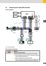
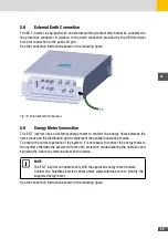
In order to minimize electromagnetic disturbances, it is required to install the EMI Suppression
Toroidal Clip Ferrite Cores supplied in the box on the cables connected to the AC GRID input.
See the following figure for installation instructions:
Fig. 14: Supression Ferrite Cores Installation for AC cables
Summary of Contents for 10ES-T
Page 1: ...Instruction Manual SolarMax ES T series 5ES T 6ES T 8ES T 10ES T ...
Page 10: ...10 3 2 Function Fig 2 Function of ES T ...
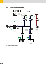
Page 22: ...22 5 2 Electrical connection diagram ES T Fig 6 Electrical connection diagram ...
Page 74: ...74 Fig 52 Login page The HOME page will appear Fig 53 HOME page ...


