29
en
5�6
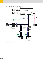
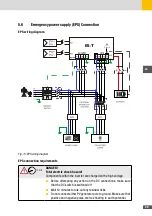
Emergency power supply (EPS) Connection
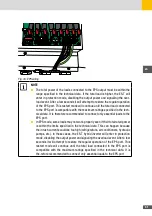
EPS wiring diagram
ES-T
Fig. 15: EPS wiring diagram
EPS connection requirements
10 min
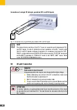
DANGER!
Fatal electric shock hazard!
Components within the inverter are charged with a high voltage.
■
Before attempting any action on the DC connections, make sure
that the DC switch is switched off
■
Wait 10 minutes to rule out any residual risks
■
Do not connect either PV generator pole to ground. Make sure that
positive and negative poles are free floating to earth potential.
Summary of Contents for 10ES-T
Page 1: ...Instruction Manual SolarMax ES T series 5ES T 6ES T 8ES T 10ES T ...
Page 10: ...10 3 2 Function Fig 2 Function of ES T ...
Page 22: ...22 5 2 Electrical connection diagram ES T Fig 6 Electrical connection diagram ...
Page 74: ...74 Fig 52 Login page The HOME page will appear Fig 53 HOME page ...

