31
en
M10
EPS
GRID
C150
C146
C144
C156
M6
M7
C162
C163
TZ14
TZ13
C152
C145
C153
C151
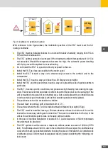
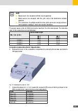
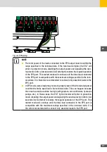
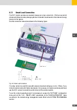
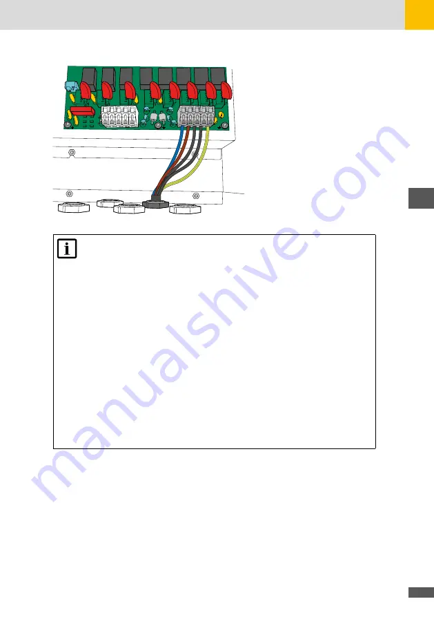
Fig. 16: EPS wiring
NOTE
■
The total power of the loads connected to the EPS output must be within the
range specified in the technical data. If the total load is higher, the ES-T will
enter in protection mode, disabling the output power and signalling the over-
load event. After a few seconds it will attempt to restore the regular operation
of the EPS port. This restart mode will continue until the total load connected
to the EPS port is compatible with the maximum ratings specified in the tech-
nical data. It is therefore recommended to connect only essential loads to the
EPS port.
■
In EPS mode, some loads may not work properly even if their total rated power
is within the limits specified in the technical data. This can happen because
the inrush currents could be too high (refrigerators, air conditioners, hydraulic
pumps, etc.). In these cases, the ES-T hybrid inverter will enter in protection
mode, disabling the output power and signaling the overload event. After a few
seconds it will attempt to restore the regular operation of the EPS port. This
restart mode will continue until the total load connected to the EPS port is
compatible with the maximum ratings specified in the technical data. It is
the-refore recommended to connect only essential loads to the EPS port.
Summary of Contents for 10ES-T
Page 1: ...Instruction Manual SolarMax ES T series 5ES T 6ES T 8ES T 10ES T ...
Page 10: ...10 3 2 Function Fig 2 Function of ES T ...
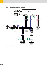
Page 22: ...22 5 2 Electrical connection diagram ES T Fig 6 Electrical connection diagram ...
Page 74: ...74 Fig 52 Login page The HOME page will appear Fig 53 HOME page ...

