40
RS485
RL4
NC NO
COM
CAN BATT
CAN EXT
LAN
RS485
RL4
NC NO CO
M
CAN BATT
CAN EXT
LAN
RS485
RL4
NC NO COM
CAN BA
TT
CAN EXT
LAN
RS485
RL4
NC NO COM
CAN BATT
CAN EXT
LAN
RS485
RL4
NC NO COM
CAN BATT
CAN EXT
LAN
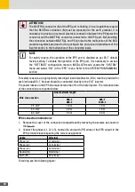
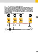
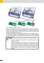
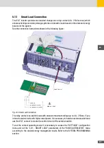
Fig. 24: ES-T connection for parallel operation
The multi-ES-T inverter system uses an external energy meter to monitor the energy flows
between the home loads and the distribution grid to implement the available operating modes.
The data from the energy meter are shared between the units connected in parallel through
the external CAN communication connection.
To set the correct operation of the system with paralleled ES-T units it is necessary to access
the “SETTINGS” configuration menu in INSTALLER mode and set the “SYSTEM” parameters
of the “IND. CAN” according to the characteristics of the system layout. Refer to the SYSTEM
PROGRAMING section.
NOTE
■
The system configuration with several ES-T units in parallel is possible up to a
maximum of 10 units.
■
The system configuration with several ES-T units in parallel can only be car-
ried out by the AC GRID port. The configuration of several units in parallel
carried out by EPS port is not permitted. Any parallel connection of multiple
units carried out by the EPS port can affect the correct functioning of the
system and relieves the manufacturer from all liabilities and invalidates the
warranty.
Summary of Contents for 10ES-T
Page 1: ...Instruction Manual SolarMax ES T series 5ES T 6ES T 8ES T 10ES T ...
Page 10: ...10 3 2 Function Fig 2 Function of ES T ...
Page 22: ...22 5 2 Electrical connection diagram ES T Fig 6 Electrical connection diagram ...
Page 74: ...74 Fig 52 Login page The HOME page will appear Fig 53 HOME page ...

