45
en
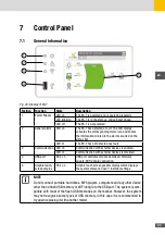
Position Function
Description
6
“BATTERY” icon
The “BATTERY” icon shows if a battery is connected to the
system. The icon also shows the battery charge / discharge
status and the percentage of energy available to the system.
The flow and the direction of energy coming from that source
is displayed on the bar located next to the icon. The numbers
shown above the bar, which can be scrolled by simply pressing
the bar itself, display in real time the voltage, current and power
values related to the battery.
7
“GRID” icon
The “GRID” icon shows if energy is being drawn from the
national grid. The flow and the direction of energy coming from
that source is displayed on the bar located next to the icon. The
numbers shown above the bar, which can be scrolled by simply
pressing the bar itself, display in real time the volta-ge, current
and power parameters of to the national grid
8
“HOME” icon
The “HOME” icon shows if there are loads which draw power
from the system. The flow of energy drawn by the residential
system is displayed on the bar located next to the icon. The
number shown above the bar displays in real time the power
drawn by the system.
9
“GENERAL ALARM”
icon
If the “GENERAL ALARM” icon is on, the system has detected a
fault. The code of the alarm detected by the system is displayed
on the system status bar (see the “Troubleshooting” section). By
touching the icon, the list of alarms recorded by the system will
be displayed.
10
“USB/WiFi” icon
Activation of the “USB” icon indicates that an external USB
memory is connected to the port on the control panel. Similarly,
the activation of the “WiFi” icon indicates that a WiFi dongle has
been connected (transparent icon) and that a connection to a
local WiFi network has been established (icon highlighted).
NOTE
The display cannot be considered a measuring instrument. The measurements
shown on the display are indicative and therefore are not suitable for calculating
the efficiency or production yield.
Summary of Contents for 10ES-T
Page 1: ...Instruction Manual SolarMax ES T series 5ES T 6ES T 8ES T 10ES T ...
Page 10: ...10 3 2 Function Fig 2 Function of ES T ...
Page 22: ...22 5 2 Electrical connection diagram ES T Fig 6 Electrical connection diagram ...
Page 74: ...74 Fig 52 Login page The HOME page will appear Fig 53 HOME page ...

