69
en
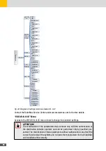
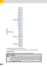
GRID CODE
VDE AR-N 4105
Capability
Interface Protection
U >
Time U >
U <
Time U <
f <
Time f <
f >
Time f >
P(f) sel.
P overF Start
P overF Stop
P underF Start
P underF Stop
S
S1
p(f) delay
V max sync
V min sync
F max sync
F min sync
U <<
Time U <<
Time U >>
U >>
cos ϕ
P(f)
cos ϕ = f(P)
Start/Sync
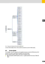
Fig. 47: Diagram of Settings Grid Code menu EN50549-1
Contact the SolarMax Service Center under www.solarmax.com for further details.
8�8
System Update
The firmware of the ES-T inverter can be updated by using an external USB memory which
must be con-nected to the USB port available on the control panel.
Before starting the system update, please note the following points:
■
Make sure that the ON/OFF switch is in the “0” position and that the inverter is STAND-BY
mode.
Summary of Contents for 10ES-T
Page 1: ...Instruction Manual SolarMax ES T series 5ES T 6ES T 8ES T 10ES T ...
Page 10: ...10 3 2 Function Fig 2 Function of ES T ...
Page 22: ...22 5 2 Electrical connection diagram ES T Fig 6 Electrical connection diagram ...
Page 74: ...74 Fig 52 Login page The HOME page will appear Fig 53 HOME page ...

