77
en
9�3
Web Portal and App Access
The SolarMax monitoring system is an integrated and online datalogging platform (for regis-
tered devices) that allows to access ES-T devices and check their operating status at any time
and from anywhere in the world if an internet connection is available.
Registered ES-T systems send operating data at regular intervals which are collected and
organized by the integrated data logger and the web portal in order to provide system status
in a simple and immediate way.
Web access can be made from the portal ( availlable under
https://portalesseries.solarmax.com
)
or via App available for Android and iOS devices and downloadable for free from the respective
online stores (Google play, App Store).
9�3�1 Getting started
NOTE
Before to access online services, it is necessary to configure the ES-T for the data
sending to the portal and check that the connection to the internet is working
properly.
Make sure that the following requirements are met:
■
The ES-T system is operating (green LED (1) blinking or steady on)
■
The WiFi connection to the local network is active (blue LED (3) on and icon (5)
highlighted).
■
The remote device (smartphone/tablet/PC/Laptop) that you want to use to access the
ES-T is connected to the same local LAN/WLAN.
Proceed following the instructions reported below:
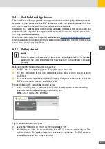
1. Enable the DLX system to send data to the portal. At this purpose, access the setting
page from the control panel through the following path:
MENU-->SETTINGS-->NETWORKING
Fig. 58: Menu to send data to the portal
2. Access the “SEND DATA TO PORTAL” menu and select “ON”
3. After having set “ON”, make sure that the blue LED (3) remains permanently on. This
confirms that the ES-T system has effective access to the internet. The ES-T system is
now enabled to send data to the web portal.
Summary of Contents for 10ES-T
Page 1: ...Instruction Manual SolarMax ES T series 5ES T 6ES T 8ES T 10ES T ...
Page 10: ...10 3 2 Function Fig 2 Function of ES T ...
Page 22: ...22 5 2 Electrical connection diagram ES T Fig 6 Electrical connection diagram ...
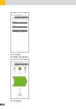
Page 74: ...74 Fig 52 Login page The HOME page will appear Fig 53 HOME page ...

