background image

94

5�  Assertion of Guarantee

For the assertion of the guarantee the SOLARMAX hotline must be contacted by phone or in written form 
and their instructions must be followed carefully. You will find the Hotline number for your country on 
our homepage. 
Please hold the series number, the article description, a short description of the defect and the purchase 
receipt ready. 
Transactions in order to solve guarantee cases carried out by the buyer without the coordination with and 
approval by SOLAR MAX will not be compensated.
In case of neglecting this procedure SOLARMAX reserves the right to decline the delivery of of the 
guarantee service.

6�  Exclusion of Guarantee

SOLARMAX reserves the right to temporarily or finally exclude the guarantee, if the parameters of the 
plant do not allow a proper function of the devices (e.g. in the event of a parameter as set out in number 
4). The exclusion of guarantee can be cancelled in accordance with SOLARMAX.
Therefore it is necessary to have a written confirmation by SOLARMAX, in order to restart the guarantee 
terms.

7�  Guarantee Extension

For devices with the Basic Guarantee BASIC the duration of guarantee can be prolonged by purchasing 
a guarantee extension within the following time periods. An extension for specific devices can be pur-
chased on the basis of limited services. The extensions being available per device can be found on our 
homepage. The purchase of a guarantee extension will be confirmed by SOLARMAX with a Guarantee 
Certificate (Series Number of Product).
In case of a replacement this certificate will not be adjusted to the new series number. In this way the 
guarantee extension stays unaffected.

a)  Time Limit for entry into Guarantee Extension

String Inverter P-,TP-, MT-, HT- Series / Junction-Box 32HT2: The extension of the guarantee can be 
purchased within 60 months starting from purchase date, but within max. 72 months after delivery of the 
device by SOLARMAX.
String Inverter of SP-,SMT-, SHT-Series: An extension of the warranty can be applied for within 6 months 
of delivery of the device by SOLARMAX.
Central Inverters:

 The extension of the guarantee can be purchased within 3 months starting from pur-

chase date, but max. 12 months after delivery of the device by SOLARMAX

b)  Scope of the Guarantee Extension

The Scope of the Guarantee Extension contains all services of the Basic Guarantee BASIC.

c)  Conclusion of a Guarantee Extension

In order to purchase a Guarantee Extension, it is necessary to fully complete and hand in a Guarantee 
Extension form.
The Guarantee Extension is completed with a written confirmation by SOLARMAX, the receipt of the 
Guarantee Certificate and the payment by the customer. 
Deviating written confirmation from SOLARMAX have priority.

8�  Conditions after the Extension of the Guarantee

The cost for repair and replacement after the extension of the guarantee period will be charged at cost. 
SOLARMAX ensures the repair and replacement ability beyond the guarantee period at its own discretion.

Summary of Contents for 10ES-T

Page 1: ...Instruction Manual SolarMax ES T series 5ES T 6ES T 8ES T 10ES T ...

Page 2: ...SolarMax Produktions GmbH Zur Schönhalde 10 D 89352 Ellzee E Mail info solarmax com SolarMax Produktions GmbH 2020 ...

Page 3: ...ivery 18 4 3 Selecting the installation location 18 4 4 Mounting the ES T 20 5 Electrical Connections 21 5 1 Safety 21 5 2 Electrical connection diagram 22 5 3 Connections in the lower part 23 5 4 PV Panels Connection 23 5 4 1 Reduction of Electromagnetic Disturbances 24 5 4 2 Connection Modes 25 5 5 AC grid Connection 26 5 6 Emergency power supply EPS Connection 29 5 7 HV Lithium Battery Connecti...

Page 4: ...ION Menu 60 8 7 4 BATTERY Menu 62 8 7 5 NETWORKING Menu 64 8 7 6 GRID CODE Menu 64 8 8 System Update 69 9 Monitoring System 71 9 1 General Information 71 9 2 Getting Started Preparing to WiFi LAN connection 71 9 2 1 Connecting to a WiFi network 72 9 2 2 WiFi LAN network settings 72 9 2 3 Direct Access over local WiFi LAN network 73 9 3 Web Portal and App Access 77 9 3 1 Getting started 77 9 3 2 Us...

Page 5: ...dustrial electronics technicians 1 3 Where to keep this manual The plant operator must ensure that this instruction manual is available to the relevant per sons at all times If this original document is lost an up to date version of this instruction manual can be downloaded from our website at any time www solarmax com 1 4 Symbols used The following safety instructions and general information are ...

Page 6: ...ard In daylight the PV generator supplies the inverter with a dangerously high DC voltage Make sure that all electrical input conductors to the inverter are de energized before starting any work on the inverter or the input conductors DANGER Fatal electric shock hazard Components within the inverter are charged with a high voltage Never open the inverter while it is in operation WARNING Risk of in...

Page 7: ...ollow the operating instructions supplied with the inverter Do not remove any symbols on the inverter Replace damaged symbols CE marking The inverter complies with the requirements of the European directives regarding the Electromagnetic compatibility and the electric safety Do not dispose of the inverter and its accessory components in the house hold waste Removing this label voids the warranty D...

Page 8: ...t to obstruct openings or cooling systems on the equipment Use suitable PPE or wait for the equipment to cool down before accessing it Lack of cleanliness this affects the cooling system and prevents the safety labels from being read Adequately clean the equipment the labels and the workplace Storage of static energy can produce dangerous electrical discharges Wait until these devices have dischar...

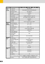
Page 9: ...t DC Max input voltage 1000 V MPPT range 150 950 V Max input current 2 x 13 A Max short circuit curr 2x 15 A Battery Nominal battery voltage 400 V Nominal battery current 25 V Output AC Nominal current 14 5 A Nominal power 100 000 VA Power factor 0 8i 0 8c Voltage 400 V 3W N PE Frequency 50 Hz Protecton class I IP rating IP21 Ambient temperature 25 60 C Compliency VDE AR N 4105 SolarMax Produktion...

Page 10: ...10 3 2 Function Fig 2 Function of ES T ...

Page 11: ...otovoltaic field is used primarily to supply the domestic loads and secondly to charge the bat tery Further energy in excess is transferred to the network If the energy required by the loads is high and the available energy from photovol taic field and battery is not enough the missing part is drawn from the network In the absence of energy from the photovoltaic field the battery is dis charged to...

Page 12: ...wn from the network The energy stored in the battery is never fed into the grid but is used exclusively to supply the home loads Battery manager mode NOTE This operating mode is mainly indicated in installations where it is convenient to the enable the battery charge during the high photovoltaic production time over the day and operate a delayed discharge of the battery when the energy demand of t...

Page 13: ...ke a predetermined time which depends on the regulations in force in the country of installation For this reason the ES T system does not guarantee the continuity of power supply to the loads con nected to it The total power of the loads connected to the EPS output must be within the range spec ified in the technical data If the total load is higher the ES T will enter in protection mode disabling...

Page 14: ...S T hybrid inverter can operate with various high voltage HV batteries which have been specifically tested and approved to ensure the safety and optimal operation of the system ATTENTION To avoid damage to the ES T hybrid inverter connect only approved battery models to the ES T hybrid inverter Contact the SolarMax service center under www solarmax com to identify the supported batteries Calibrati...

Page 15: ...X hybrid inverter to carry out a maintenance charge The maintenance charge status is shown on the display status bar ATTENTION The maintenance charge is a safety function of the battery to avoid damages For this reason the ES T hybrid inverter can activate grid charging if the avail able solar energy is not enough During the maintenance charge normal system functionalities are disabled and the bat...

Page 16: ...U in compliance with the requirements of IEC EN 62109 2 safety standard The device in question only protects the system from earth leakages occurring upstream of the AC OUT terminals i e towards the DC side of the PV system and the refore towards the PV panels Leakage currents that could occur in the AC section between the PPC Point of Common Coupling point and the ES T are not detected and requir...

Page 17: ...emains operational even if it appears to be off To reactivate it simply touch the display surface 4 Installation NOTE The installation must be carried out only by experienced staff authorized by the manufacturer 4 1 Lifting and Transport instructions Transport and Handling Transport of the equipment especially on the road must be carried out with means able to protect the system components especia...

Page 18: ...g comoonents have to be contained in the scope of delivery ES T hybrid inverter Top and bottom bracket for wall mounting Support for wall mounting Instruction manual Quick connectors and related contacts for PV strings wiring and connection Quick connectors and related contacts for BATTERY wiring and connection Ferrite cores kit for EMI suppression Wi Fi dongle for connection to a local wireless n...

Page 19: ...t buzzing noise during its oper ation This noise is normal and does not affect its performance but can be annoying if the unit is mounted onto a wall of an inhabited area onto a wall adjacent to an inhabited area or onto certain type of materials such as thin wooden panels or metal plates The position must not be accessible to children The wall must be vertical with a maximum tilt of 5 The surface...

Page 20: ...red with a wall mounting bracket suitable for use on most walls 220 4 x Ø5 2 366 663 Fig 4 Mounting bracket on the rear panel of the ES T Do the following steps to mount the ES T to the wall 1 4 x 2 3 4 5 6 4 x 2 x 2 x Fig 5 Mounting Steps 1 Fix the top and bottom mounting brackets to the ES T body 2 Drill the holes to fix the ES T mounting support on the wall 3 Fix the mounting support to the wal...

Page 21: ... observing the local and national standards and regulations The PV generator voltages are very high NEVER plug or unplug the DC con nectors when the inverter is turned on otherwise dangerous electric arcs could develop 10 min DANGER Fatal electric shock hazard Components within the inverter are charged with a high voltage Before attempting any action on the DC connections make sure that the DC swi...

Page 22: ...22 5 2 Electrical connection diagram ES T Fig 6 Electrical connection diagram ...

Page 23: ...tput 7 EPS output 8 Energy meter and battery BMS wiring input 9 LAN and AUX wiring input 10 CAN wiring input 5 4 PV Panels Connection DANGER Fatal electric shock hazard In daylight the PV generator supplies the inverter with a dangerously high DC voltage The PV generator voltages are very high NEVER plug or unplug the DC con nectors when the inverter is turned on otherwise dangerous electric arcs ...

Page 24: ...e ES T determined at the minimum rated temperature for operation must NEVER exceed 1000V Exceeding the limit can cause serious damage to the ES T 5 4 1 Reduction of Electromagnetic Disturbances NOTE The ES T may be not compliant with the EMC standards requirements if the ferrite cores are not installed according to the instructions provided In order to minimize electromagnetic disturbances it is r...

Page 25: ...uctions for PV panels Connection of independent PV strings to PV1 and PV2 inputs PV1 PV2 _ _ Fig 9 Connection of independent PV strings to PV1 and PV2 inputs Connection of a single PV string to the PV1 or PV2 input PV _ _ Fig 10 Connection of a single PV string to the PV1 or PV2 input ...

Page 26: ... MPPT parameter in PARALLEL mode in the MPPT CONF menu Refer to the SYSTEM PROGRAMMING section 5 5 AC grid Connection 10 min DANGER Fatal electric shock hazard Components within the inverter are charged with a high voltage Before attempting any action on the DC connections make sure that the DC switch is switched off Wait 10 minutes to rule out any residual risks Do not connect either PV generator...

Page 27: ...nection are reported below Wire cross section Line maximum length 5ES T 6ES T 8ES T 10ES T 2 5 mm2 18 m 12 m 4 0 mm2 29 m 19 m 6 0 mm2 45 m 30 m Connection instructions for AC Output Cables 6 Remove the cover of the connection compartment by removing the screws as shown in the figure below Fig 12 Removing the cover of ES T 7 Connect the phase L1 L2 L3 neutral N and earth PE wires of the AC grid in...

Page 28: ...ing the problem with a specific alarm code Reduction of Electromagnetic Disturbances NOTE The ES T may be not compliant with the EMC standards requirements if the ferrite cores are not installed according to the instructions provided In order to minimize electromagnetic disturbances it is required to install the EMI Suppression Toroidal Clip Ferrite Cores supplied in the box on the cables connecte...

Page 29: ...ric shock hazard Components within the inverter are charged with a high voltage Before attempting any action on the DC connections make sure that the DC switch is switched off Wait 10 minutes to rule out any residual risks Do not connect either PV generator pole to ground Make sure that positive and negative poles are free floating to earth potential ...

Page 30: ...in INSTALLER mode access the SYSTEM menu and select ON in the EPS menu Refer to the SYSTEM PROGRAMMING section For safety reasons an appropriately rated input load disconnector 20 A must be provided for each individual ES T No load should be connected directly to the ES T inverter The power losses on the EPS line must be less than 1 of the rated power The indicative data of the connection are repo...

Page 31: ...ch nical data It is therefore recommended to connect only essential loads to the EPS port In EPS mode some loads may not work properly even if their total rated power is within the limits specified in the technical data This can happen because the inrush currents could be too high refrigerators air conditioners hydraulic pumps etc In these cases the ES T hybrid inverter will enter in protection mo...

Page 32: ...attery cables are disconnected from the bat tery and that the poles are insulated to prevent short circuits Make sure that the AC GRID and EPS circuit breakers are disconnected ATTENTION Use battery cables with cross section of 6 mm2 and with a maximum length of 3 m per cable Use in the quick connectors supplied to connect the cables to the battery inputs of the ES T Failure to comply with the fol...

Page 33: ...on connector For the appropriate settings refer to the SYSTEM PRO GRAMMING section BATTERY paragraph 4 Where required connect the battery cables to the battery according to the manufacturer s instructions and using any connectors provided in the battery connection kit ATTENTION During the wiring operations isolate the battery poles to prevent short cir cuits Shorted poles can cause sparks fire haz...

Page 34: ...t installed according to the instructions provided In order to minimize electromagnetic disturbances it is required to install the EMI Suppression Clip Ferrite Core supplied in the box on the cables connected to the BAT input See the following figure for installation instructions Fig 18 Supression Ferrite Cores Installation for battery cables ...

Page 35: ...ternal energy meter to monitor the energy flows between the home loads and the distribution grid to implement the available operating modes To ensure the correct operation of the system it is necessary to connect the energy meter to the inverter otherwise the system will enter into protection mode disabling the operation and signaling the failure to communicate with the device NOTE The ES T invert...

Page 36: ...36 RS485 RL4 NC NO COM CAN BATT CAN EXT LAN Meter Communication Fig 20 Connection instructions for energy meter ...

Page 37: ...n menu SETTINGS and set the networking parameters of the WLAN menu according to the characteristics of the local net work to be accessed Refer to the SYSTEM PROGRAM MING NETWORKING section 3 If the configuration operations are carried out correctly the effective connection to the local WiFi network is shown by the WiFi icon icon highlighted on the status bar of the display and by the stable lighti...

Page 38: ...owing figure RS485 RL4 NC NO COM CAN BATT CAN EXT LAN Cloud LAN Cable Router LAN Cable Fig 22 LAN connection instruction 2 To set the correct operation of the connection it is necessary to access the SETTINGS configuration menu and set the networking parameters of the LAN menu based on the characteristics of the local network to be accessed Refer to the SYSTEM PROGRAMMING NETWORKING section 3 If t...

Page 39: ...n parallel The respective HV battery is connected to each ES T inverter The energy management between the various devices and batteries is managed in MASTER and SLAVE mode where one of the inverters acts as MASTER unit and the other inverters operate as SLAVE units See the connection instructions shown in the following figures CAN CAN CAN CAN INV_1 MASTER INV_2 SLAVE INV_3 SLAVE INV_10 SLAVE METER...

Page 40: ...the correct operation of the system with paralleled ES T units it is necessary to access the SETTINGS configuration menu in INSTALLER mode and set the SYSTEM parameters of the IND CAN according to the characteristics of the system layout Refer to the SYSTEM PROGRAMING section NOTE The system configuration with several ES T units in parallel is possible up to a maximum of 10 units The system config...

Page 41: ... COMMON MAX 4A 250V NO NORMALLY OPEN NC NORMALLY CLOSED Fig 25 Smart Load Connection The relay contact can switch loads with absolute maximum ratings up to 4A 250Vac If you intend to control loads with higher rated power it is necessary to install an external switch and use the ES T contact to create the control circuit of the external switch To set the contact operating mode it is necessary to ac...

Page 42: ...ttery 5 Wait for the display to turn on 6 Start the inverter by turning the ON OFF switch in position 1 AUTO TEST execution Italy CEI 0 21 The self test is relevant only for Italy CEI 021 If the ES T is configured for Italy the self test is available through the service menu on the display The self test for Italy is aimed at verifying the upper and lower limits of the voltage and frequency of the ...

Page 43: ...munication LED on Communication with external devices is enabled LED of Communication with external devices is disabled 4 USB port ES T on USB port available for data download firmware update WiFi dongle connection 5 Graphic touch screen display ES T on Graphic touch screen graphic display which displays the system status and user installer settings NOTE Do not connect portable hard disks MP3 play...

Page 44: ...data and statistical data system configuration and programming menus 3 Access to the LOGIN This key allows the operator to view the login page to access the different programming level of the system by entering the access password 4 ENERGY BALANCE icon This dynamic icon shows the system energy balance in real time the green colour shows the percentage of energy produced by renewable sources PV and...

Page 45: ...id 8 HOME icon The HOME icon shows if there are loads which draw power from the system The flow of energy drawn by the residential system is displayed on the bar located next to the icon The number shown above the bar displays in real time the power drawn by the system 9 GENERAL ALARM icon If the GENERAL ALARM icon is on the system has detected a fault The code of the alarm detected by the system ...

Page 46: ... CHARTS INFO EXPORT SETTINGS 24h 7d 12M SYSTEM PARAMETERS FW VERSION NETWORKING DATA EVENTS GENERAL PLANT HOME AUTOMATION BATTERY NETWORKING GRID CODE MENU Fig 28 Structure of the menus To access the menus marked with it is necessary to perform the LOGIN as INSTALLER with password which must be compulsorily requested from the manufacturer ...

Page 47: ...key By pressing this key the identification page can be accessed with password or the installer mode can be exited 4 CHARTS key By pressing this key the related menu can be accessed 5 INFO key By pressing this key the related menu can be accessed 6 SETTINGS key By pressing this key the related menu can be accessed 7 EXPORT key By pressing this key the related menu can be accessed 8 KEY icon The ic...

Page 48: ...g 30 Login Menu Position Function Description 1 Numeric keypad Numeric keypad to enter the ID password 2 BACKSPACE Key ress this key to delete the last digit entered 3 ENTER Key Enter Submit key 8 4 CHARTS Menu Access to the CHARTS menu allows the installer to view the following data recorded by the built in datalogger Daily time related data of PV system battery grid load powers Weekly calculatio...

Page 49: ...y to select the different chart 24 hours 7 days 12 months 2 HOME key Press this key to enable disable the display of the associated value and trace on the graphics area 3 SUN key Press this key to enable disable the display of the associated value and trace on the graphics area 4 GRID key Press this key to enable disable the display of the associated value and trace on the graphics area 5 BATTERY ...

Page 50: ...iated value and trace on the graphics area 3 SUN key Press this key to enable disable the display of the associated value and trace on the graphics area 4 GRID CONSUMP TION key Press this key to enable disable the display of the associated value and trace on the graphics area 5 GRID FEED IN key Press this key to enable disable the display of the associated value and trace on the graphics area 8 4 ...

Page 51: ...ociated value and trace on the graphics area 3 SUN key Press this key to enable disable the display of the associated value and trace on the graphics area 4 GRID CONSUMP TION key Press this key to enable disable the display of the associated value and trace on the graphics area 5 GRID FEED IN key Press this key to enable disable the display of the associated value and trace on the graphics area ...

Page 52: ...WORKING INFO Serial Number AC Inv Temp PV Temp CHG Temp Battery Temp R iso PV1 R iso PV2 R iso COM R iso BAT R iso BAT I diff I diff Test L ION Info Device FW DSP A FW DSP B FW DSP C FW DSP D FW Disp FW LAN WLAN IP Address IP Address Netmask Gateway Netmask Gateway Signal dBm SSID Fig 35 Diagram of Chart menu ...

Page 53: ...ff Test Measured test leakage current to earth L ION info Battery info if transmitted by battery BMS 8 5 2 FW Version The page displays the firmware versions installed on the system Parameter Description Device FW Main inverter firmware DSP A FW DSP A Firmware DSP B FW DSP B Firmware DSP C FW DSP C Firmware DSP D FW DSP D Firmware Disp FW UI firmware 8 5 3 Networking The page displays the informat...

Page 54: ...mory Enter the start and end dates to define the time period to download the data Events The page allows to access the download function of the events alarm queue parameter modification recorded by the system on an external USB memory Enter the start and end dates to define the time period to download the data NOTE Make sure to have connected an external USB memory before performing the export pro...

Page 55: ...he home automation functions setting BATTERY The page allows to access the battery settings Some of the settings are accessible only in the INSTALLER mode which require a password to be logged in see the LOGIN menu section NETWORKING The page allows to access the settings to connect the system to a local data network LAN or WiFi Some settings are accessible only in the INSTALLER mode which require...

Page 56: ...tion AUTOTEST The page allows to start the self test and verify its correct execution It is also possible to export the complete self test report to external USB memory The self test procedure is only relevant for Italy CEI 0 21 It is possible to export the complete self test report in TXT format to external USB memory Make sure to connect an external USB memory before carrying out the export proc...

Page 57: ...f the fans Extra Settings 0 99999 The EXTRA parameters must be used only by qualified staff ATTENTION The parameters must be accessed only by qualified staff Changing the param eters at the installer level by unqualified staff can affect the correct functioning of the system and relieves the manufacturer from all liabilities and invalidates the warranty ...

Page 58: ... password to be logged in see the LOGIN menu section SETTINGS MPPT Conf V AC Nom F AC nom Ifv1 Tar Ifv2 Tar CAN Addr EPS Energy Meter Setup PV Meter Setup AC Hybrid Backup Reserve Feed in Control PLANT Indip Parall TA Ext Meter Ext PV Meter Ext PV Meter Type PV Meter Add Backup Reserve Sel SOC Backup Reserve Feed in Limit Sel P Limit Fig 39 Diagram of Settings plant menu ...

Page 59: ...gs in the case of systems consisting of several units in parallel according to the following table PARAMETER VALUE DESCRIPTION CAN Addr 0 Single unit default 1 MASTER unit 2 10 SLAVE unit EPS The page allows to enable disable the EPS functionality PARAMETER VALUE DESCRIPTION EPS ON OFF EPS port operation enable Default OFF ENERGY METER SETUP The page allows to configure the functionality of the en...

Page 60: ...EED IN CONTROL The page allows to enable disable the FEED IN CONTROL mode to limit the injection of the energy produced into the network and to set the limit value PARAMETER VALUE DESCRIPTION Feed in Sel ON OFF FEED IN CONTROL operation enable Default OFF P Limit 0 10 000 W Limit of the power fed into the grid DEFAULT 0 8 7 3 HOME AUTOMATION Menu ccess to the HOME AUTOMATION menu allows to configu...

Page 61: ...t the SMART LOAD operating mode for the load controlled by the isolated changeover contact 4A 250Vac max available in the ES T Through the contact it is possible to enable secondary storage systems and or domestic loads based on the status and energy balance of the system PARAMETER VALUE DESCRIPTION LD On Off ON OFF LD program enable Default OFF LD P sel PV GRID Selection of the activating power t...

Page 62: ...e The settings are accessible only in the INSTALLER mode which require a password to be logged in see the LOGIN menu section PARAMETER VALUE DESCRIPTION Battery Manager Sel ON OFF BATTERY MANAGER operation enable Default OFF Batt Disch Start Time hh mm Battery discharge start time Batt Disch Stop Time hh mm Battery discharge stop time Batt Ch Start Time hh mm Battery charge start time 8 7 4 BATTER...

Page 63: ...s the ES T system to interact exclusively with the type brand and model of battery selected CH DISCH PAR The page allows to set the maximum charge and discharge current The set value represents the maximum value allowed by the inverter The charge discharge setpoint is anyway defined by the battery BMS which is based on the state of charge and the temperature of the battery itself PARAMETER VALUE D...

Page 64: ...k it is necessary to specify IP AD DRESS NETMASK and GATEWAY WLAN The page allows you to set the network parameters for access to a wireless local area network with WiFi connection PARAMETER VALUE DESCRIPTION SSID Automatic scan for available wireless networks and network selection Password Network password setting Network Static DHCP Network parameter setting Default DHCP In the case of a STATIC ...

Page 65: ...ameter setting PARAMETER VALUE DESCRIPTION CEI 0 21 CEI 0 21 IT enable and parameters setting VDE AR N 4105 VDE AR N 4105 DE enable and parameters setting G98 G99 G98 G99 UK enable and parameters setting EN 50549 1 EN 50549 1 enable and parameters setting See the following sections for detailed diagrams of grid code parameters CEI 0 21 Menu Access to the CEI 0 21 menu allows to change the standard...

Page 66: ...QDelaya CurvaQKa P sottoF Start Lim P V Lim P Lim Q P f Capability cos ϕ f P Curva A Avv Sinc GRID CODE Fig 44 Diagram of Settings Grid Code menu CEI 0 21 Contact the SolarMax Service Center under www solarmax com for further details VDE AR N 4105 Menu Access to the VDE AR N 4105 menu allows to change the standard settings ATTENTION The modification of the parameters shall be made only with the au...

Page 67: ...105 Contact the SolarMax Service Center under www solarmax com for further details G98 G99 Menu Access to the G98 G99 menu allows to change the standard settings ATTENTION The modification of the parameters shall be made only with the authorization of the distribution network operator and can be performed only by qualified per sonnel The modification of these parameters without authorization can a...

Page 68: ...e Center under www solarmax com for further details EN 50549 1 Menu Access to the EN 50549 1 menu allows to change the standard settings ATTENTION The modification of the parameters shall be made only with the authorization of the distribution network operator and can be performed only by qualified per sonnel The modification of these parameters without authorization can affect the correct functio...

Page 69: ...Sync Fig 47 Diagram of Settings Grid Code menu EN50549 1 Contact the SolarMax Service Center under www solarmax com for further details 8 8 System Update The firmware of the ES T inverter can be updated by using an external USB memory which must be con nected to the USB port available on the control panel Before starting the system update please note the following points Make sure that the ON OFF ...

Page 70: ...ure could affect the correct operation of the system and relieves the manufacturer from all liabilities as well as invalidate the warranty Do not remove the external USB memory during the update procedure Removal of the external USB memory during the update could affect the cor rect operation of the system and relieves the manufacturer from all liabilities as well as invalidate the warranty 1 Acce...

Page 71: ... by the integrated data logger and the SolarMax portal in order to provide system status in a simple and immediate way There are two types of remote access to ES T systems Direct access on local WiFi LAN network via web browser Web access via portal or via SolarMax App available for Android and iOS devices on local WiFi LAN network with internet access 9 2 Getting Started Preparing to WiFi LAN con...

Page 72: ...ion to be established blue LED 3 on and icon 5 highlighted 6 The ES T system is now connected to the WiFi network of the selected router 9 2 2 WiFi LAN network settings Based on the connection you made access the NETWORK menu to perform the WiFi LAN network settings by following the following paths MENU SETTINGS NETWORKING WLAN NETWORK MENU SETTINGS NETWORKING LAN NETWORK Fig 50 WLAN network setti...

Page 73: ...ess over local WiFi LAN network The following remote access mode to the ES T system allows to get the system control panel onto the device used for the remote connection No parameters changes are allowed on the remote control panel but only system checks Make sure that the following requirements are met The ES T system is operating green LED 1 blinking or steady on The WiFi connection to the local...

Page 74: ...74 Fig 52 Login page The HOME page will appear Fig 53 HOME page ...

Page 75: ...ection of the system Fig 54 HOME page CHARTS menu Access to the CHARTS menu allows you to view the data stored by the integrated data logger with the same functionality provided by the ES T control panel Refer to the ES T user manual for operating details Fig 55 Charts viewer ...

Page 76: ... general system information Refer to the EST user manual sections for operating details Fig 56 Info menu USER menu Access the USER menu to change the default access password PASSWORD CHANGE menu or to disconnect from the system LOGOUT menu Fig 57 User menu ...

Page 77: ...s it is necessary to configure the ES T for the data sending to the portal and check that the connection to the internet is working properly Make sure that the following requirements are met The ES T system is operating green LED 1 blinking or steady on The WiFi connection to the local network is active blue LED 3 on and icon 5 highlighted The remote device smartphone tablet PC Laptop that you wan...

Page 78: ...TE Before being able to access the online services it is necessary to create an user account through the regi stration procedure available on the portal page Proceed the following instructions reported below 1 Access the web portal via smartphone tablet PC Laptop by typing the following address on the web browser www solarmax com 2 Access the registration page and fill out the proposed form 3 Afte...

Page 79: ...to life due to improper handling of batteries The ES T system can operate with high voltage HV lithiumion batteries Batteries produce electricity and can cause electric shock or fire in the event of a short circuit or incorrect installation Before connecting the battery to the ES T system make sure to have read and understood all the instructions provided in the operating and installation manual s...

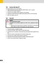
Page 80: ... supplies the inverter with a dangerously high DC voltage Make sure that all electrical input conductors to the inverter are de energized before starting any work on the inverter or the input conductors 1 Proceed as follows to uninstall the system 2 Disconnect the battery cable connectors from the BAT inputs 3 Disconnect the DC connectors of the photovoltaic panel strings from the inputs PV1 and P...

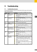
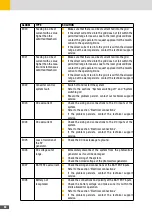
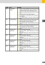
Page 81: ...ections to the system Refer to the section Electrical connections If the problem persists contact the technical support service E005 Faulty protection interface device inte grated in the system Switch off and restart the system Refer to the sections System switching off and System switching on Should the problem persist contact our technical support service E006 Faulty interlock device integrated ...

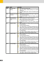
Page 82: ...nection point or request approval for the change to the operating limits If the mains voltage is within the allowed range but the alarm persists contact the technical support service E012 High grid voltage Make sure that the mains voltage is within the range allowed by local regulations Check the network impedance If the mains voltage is not within the permitted range for reasons due to the local ...

Page 83: ...he grid frequency is not within the permitted range for reasons due to the local grid conditions contact the grid operator to request approval for the change to the operating limits If the grid frequency is within the allowed range but the alarm persists contact the technical support service E017 High grid frequency Make sure that the grid frequency is within the range allowed by local regulations...

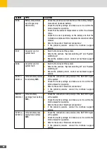
Page 84: ... restart the system Refer to the sections System switching off and System switching on Should the problem persist contact our technical support service E023 DC overcurrent Check the sizing and connections to the DC inputs of the system Refer to the section Electrical connections If the problem persists contact the technical support service E024 DC overcurrent Check the sizing and connections to th...

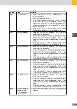
Page 85: ...and the output connections to the system Refer to the section Electrical connections If the problem persists contact the technical assistance service E032 Converter control system fault Switch off and restart the system Refer to the sections System switching off and System switching on Should the problem persist contact our technical support service E033 Converter control system fault Switch off a...

Page 86: ...g off and System switching on Should the problem persist contact our technical support service E001LI E0031LI Lithium battery alarms from battery BMS Check the connections and polarity at the BATTERY inputs of the system Check the battery voltage and make sure it is within the limits allowed for operation Refer to the section Electrical connections If the problem persists contact the technical sup...

Page 87: ...lp you We need the following information from you Device type Serial number S N Installation location Information on the present failure status message etc Availability The contact details of the SolarMax Service Center can be found overleaf or at www solarmax com SolarMax Produktions GmbH Zur Schönhalde 10 D 89352 Ellzee ...

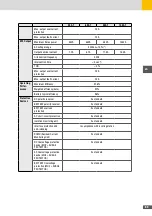
Page 88: ...nce 5kW MPPT1 2 5kW MPPT2 6 5kW MPPT1 2 5kW MPPT2 8 5kW MPPT1 3 5kW MPPT2 10kW MPPT1 5kW MPPT2 Maximum input current x MPPT 13A Short circuit current x MPPT 15A Number of MPPTs 2 Maximum number of strings x MPPT 1 1 Maximum backfeed current to PV array 0V Battery charge Battery type Lithium Battery voltage range 170V 500V Max charging discharging current 25A Nominal battery voltage 200V 240V 320V ...

Page 89: ...97 6 Weighted effciency Euro 97 Battery typical effciency 96 Protective Devices DC polarity reversal As standard BATTERY polarity reversal As standard BATTERY overload protection As standard AC short circuit protection As standard Isolation monitoring unit As standard Interface protection and anti islanding In compliance with local legislation RCMU Residual Current Monitoring Unit As standard DC O...

Page 90: ... temperature 30 C 70 C Relative humidity 5 95 without condensation Noise levels 50 dB A 1m Maximum operating alti tude without derating 2000m Pollution degree classifcation PD 3 Installation environmental category Indoor unconditioned General data Protection rating IP 21 Overvoltage category IEC 62109 1 II DC BATTERY inputs III AC output Cooling concept I cool forced cooling Dimensions W x H x D m...

Page 91: ...s national law electrical equipment that has reached the end of its useful life and discharged batteries must be separated from general waste and disposed to the appropriate authorized collection and recycling centers Any device that is no longer needed must therefore be returned to the distributor or disposed to an authorized collection and recycling center in your area Ignoring this European Dir...

Page 92: ... 24 months from purchase date but max 30 months after delivery of device by SOLARMAX Junction Box 32HT2 60 months from purchase date but 72 months after delivery of device by SOLARMAX Deviating written confirmation from SOLARMAX have priority b Scope of Guarantee BASIC If a device shows a defect or malfunction within the duration of guarantee and if the conditions for the assertion of warranty as ...

Page 93: ...o replacement material available at a reasonable expense SOLARMAX is authorized to replace the defect device In this case the above mentioned terms of replacement are applicable 3 Duration of Guarantee for Device Repair Device Replacement In case of repair or replacement of devices within the scope of the guarantee the remaining duration of guarantee of the original device applies to the repaired ...

Page 94: ...page The purchase of a guarantee extension will be confirmed by SOLARMAX with a Guarantee Certificate Series Number of Product In case of a replacement this certificate will not be adjusted to the new series number In this way the guarantee extension stays unaffected a Time Limit for entry into Guarantee Extension String Inverter P TP MT HT Series Junction Box 32HT2 The extension of the guarantee ...

Page 95: ...n shall exclusively be Augsburg Germany as far as this is permitted by law Appendix Country List Austria Belgium Bulgaria Czech Republic Denmark France Germany Greece Italy Liechstenstein Luxembourg Netherlands Poland Portugal Slovakia Slovenia Spain Sweden Switzerland United Kingdom Issued 04 2019 subject to modifications ...

Page 96: ...07840 CH 41 315281165 ES 34 93 2203859 GB 44 20 38080346 IT 39 0418520076 FR 33 820 420 684 Fax 49 3733 50784 99 Mail hotline solarmax com SolarMax Service Center You will find all contact information on our website www solarmax com ...

Reviews: