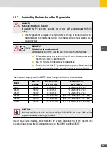
19
en
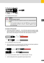
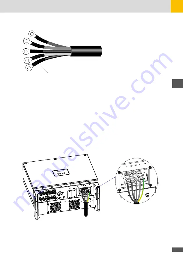
Heat shrink tubing
Fig. 11: Connecting the OT terminals to the AC cable
4. Loosen the four screws of the AC cover on the inverter and remove the cover.
5. Push the AC cable through the opening in the cable cover from behind. The cable must be
pulled through so that the conductors can be connected to the termination strip of the
inverter.
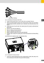
6. Connect the wires of the AC cable to the terminal strip of the inverter as described and
shown below:
■
Phase L1 to the first screw terminal L1
■
Phase L2 to the second screw terminal L2
■
Phase L3 to the third screw terminal L3
■
Neutral conductor N (black) to the fourth screw terminal N
■
Protective earth conductor PE (yellow-green) to the fifth screw terminal with the earthing
symbol.
Use a screw driver to tighten screws on the termination strip.
Fig. 12: Assignment of connecting terminals
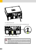
7. Lock the AC output terminal shell back to the original position, stretch all the wires on the
AC end naturally and then tighten the plug (see following figure).
Summary of Contents for 17SHT
Page 1: ...Instruction Manual SolarMax SHT series 17SHT 20SHT 22SHT 25SHT 28SHT 30SHT...
Page 4: ...4...
Page 39: ...39 en...

