23
en
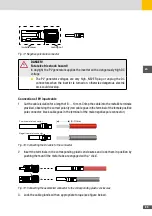
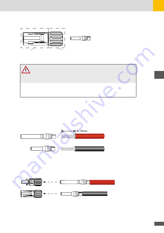
Insulation layer
Locking nut
Fig. 17: Negative pole male connector
DANGER!
Fatal electric shock hazard!
In daylight the PV generator supplies the inverter with a dangerously high DC
voltage.
■
The PV generator voltages are very high. NEVER plug or unplug the DC
connectors when the inverter is turned on, otherwise dangerous electric
arcs could develop.
Connection of PV input cable
1. Cut the cable isolation for a length of 8 … 10 mm. Crimp the cable into the metallic terminals
provided, observing the correct polarity (red cable goes in the terminal of the female positive
pole connector; black cable goes in the terminal of the male negative pole connector).
Positive metal connector
Negative metal connector
Fig. 18: Connecting the DC cable to the connector
2. Insert the terminals in the corresponding plastic enclosures and lock them in position by
pushing them until the metal tabs are engaged with a “click”.
Fig. 19: Connecting the assembled connector to the corresponding plastic enclosures
3. Lock the cable glands with an appropriate torque (see figure below).
Summary of Contents for 17SHT
Page 1: ...Instruction Manual SolarMax SHT series 17SHT 20SHT 22SHT 25SHT 28SHT 30SHT...
Page 4: ...4...
Page 39: ...39 en...


