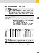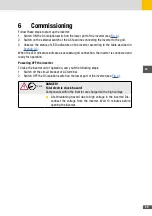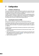
24
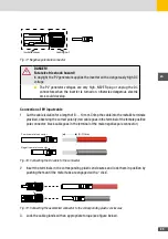
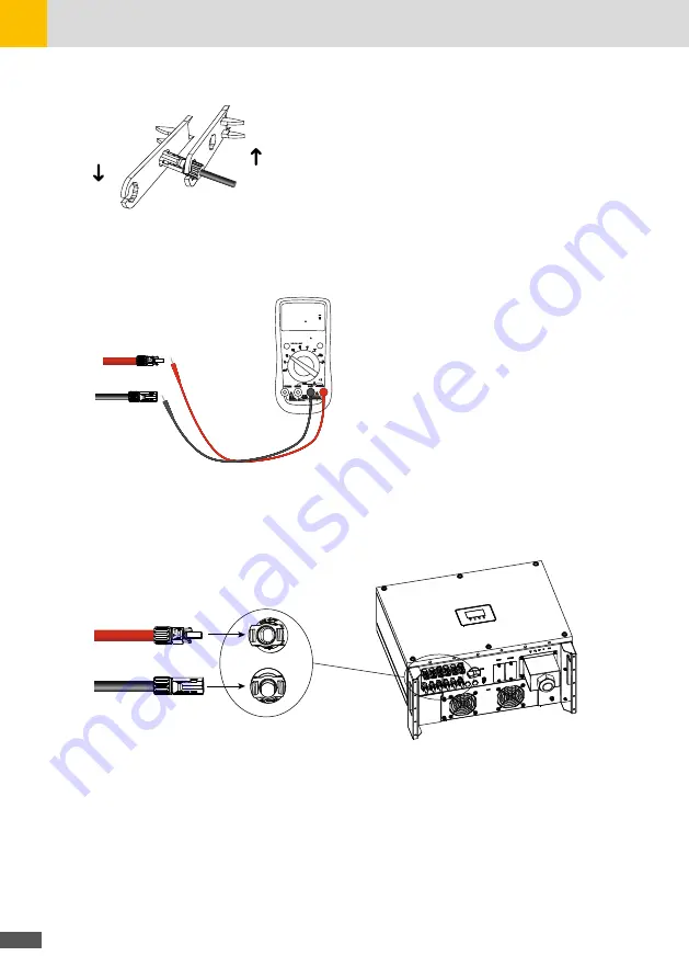
Fig. 20: Locking the cable glands
4. Check with a voltmeter of proper scale that the polarities and the DC voltage values are
correct.
RANGE
MAXMI N
REL
Hz %
P
C
800 00
Fig. 21: Checking DC voltage values with a voltmeter
5. Insert the connectors into the respective counterparts located at the bottom of the inverter
and push them until they are locked by a “click” of the plastic side tabs.
PV–
PV+
P
C
Fig. 22: Connecting the assembled cable to the SHT inverter
6. After connecting the PV strings, ensure that all connectors are in position by checking for
resistance when a slight pull is applied.
5�3
Communication interface
WIFI module implements communication with cloud server through
wireless network to monitor PV inverter‘s data status.
For more details, refer to WIFI product application manual.
Summary of Contents for 17SHT
Page 1: ...Instruction Manual SolarMax SHT series 17SHT 20SHT 22SHT 25SHT 28SHT 30SHT...
Page 4: ...4...
Page 39: ...39 en...

