26
5.2.1 General connection conditions
The following connection conditions apply to both single-tracking and multi-tracking
compact stations.
■
■
Maximum DC input voltage: 900 V
■
■
For longer connection distances, use larger conductor cross-sections in order to keep
transmission losses to a minimum.
■
■
The DC inputs of the inverters include type 2 overvoltage protection.
■
■
Maximum permissible excess of PV generator output: 50%
5.2.2 Connection of single-tracking compact stations
This chapter describes the DC connection of single-tracking compact stations.
Connecting conditions
■
■
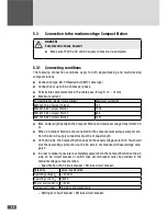
A maximum of 14 DC conductors can be connected
■
■
Maximum DC input current: 160 A (per DC input)
■
■
The DC input at the extreme right (No. 6) must not be used.
■
■
Conductor cross-sections: min. 95 mm
2
/ max. 240 mm
2
■
■
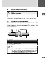
Cable diameters that can be pulled through the cable pass-through elements: 12 ...
31 mm
Procedure
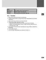
1. Remove the protective cover from the NH fuse circuit breaker (8 x M6 cap nuts)
2. Pull the DC supply conductors through the cable pass-through elements as described
in Section 5.1.
3. Install the DC supply conductors to the DC terminals.
4. Remove the covers from the DC terminals.
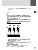
5. Connect the DC supply conductors to the M12 terminals:
– isolate cable over 25 mm.
– Tightening torque 32 Nm
– Ensure correct polarity.
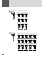
– If you do not use all DC inputs, connect the DC inputs starting from the middle
group of terminals (No. 4):

