28
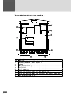
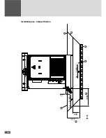
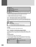
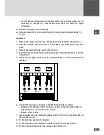
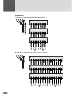
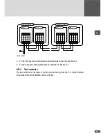
No.
Description
2
DC power bus bars
3
Connection of inverter 1 (hard-wired)
4
Middle terminal group
5
Connection of inverter 2 (hard-wired)
5
NH fuse circuit breaker for DC overvoltage protection / do not connect any DC supply
conductors!
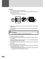
6. Do not fix a cable strain relief device on the rail below the DC terminals.
7. Replace all protective covers over the DC terminals.
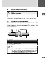
8. Install the cable pass-through elements as described in Section 5.1.
5.2.3 Removing the panels from the Compact Station
When carrying out electrical installations or maintenance work, the side panels must be
removed from the Compact Station. The panels are mounted with M8 hexagon socket
screws.
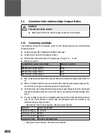
CAUTION!
Risk of injury!
The panels weigh over 25 kg each.
■
■
At least 2 persons are required for lifting the panels.
Procedure
First remove the top side panel, then the bottom side panel.
5.2.4 Connection of multi-tracking compact stations
This chapter describes the DC connection of multi-tracking compact stations. In multi-
tracking applications, the DC supply conductors are connected at the DC terminals in the
inverters.
Connecting conditions
■
■
Maximum DC input current: 240 A (per DC input)
■
■
Up to 3 DC supply conductors can be connected in parallel to each power unit (PU).
■
■
When connecting 3 DC supply conductors to each power unit, a larger conductor
cross-section is required due to reverse currents:
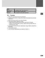
Number of DC supply conductors per
power unit
Minimum conductor cross-section
1
95 mm
2
2
50 mm
2
3
70 mm
2

