34
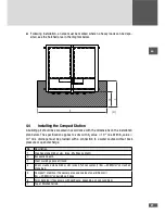
3.4) at the hollow base of the Compact Station.
Tightening torque: 72 Nm
5.5
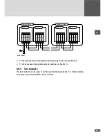
Wiring the MCU interfaces
The MCU has interfaces for remote monitoring, emergency shutdown and data commu-
nication (only master station).
1
1
1
- +
Solarpark X821
Ethernet X601
modularTS
MCU Mode S231
Num of LTs S241
X802
Status Relais X411
Externer Alarm X501
WR-Freigabe X511
MaxComm X621
Anschluss PAS X2201
MCU100
1
1
2
3
4
5
6
7
No.
Description
1
Connection of potential equalization set (X2201)
2
Alarm contact (X501)
3
Shutdown 2 (X511)
4
Status signaling contact (X411)
5
Rotary switch S241 ("Num of LTs": number of power units)
6
RJ45 Ethernet socket
7
RJ45-RS485 socket
5.5.1 Cable installation
The cable is installed in the cable duct beneath the MCU and through the small cable
pass-through element in the connection area of the Compact Station (see Section 3.4).
The cables must be fully installed and fixed inside and outside the Compact Station. Then
the cable pass-through element must be fitted as described in Section 5.1.
5.5.2 Status signaling contact - X411
The status signaling contact is used for remote monitoring of the Compact Station. The
status of the Compact Station (mains connected or disconnected) can be established
using the potential-free relay contact. This function is adjustable, see Section 6.3.3.


