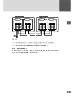
36
■
■
Permissible cable diameters in the small cable pass-through: 8 …18 mm
■
■
Maximum cable length: 50 m
5.5.5 Potential equalization set PAS – X2201
This is the interface for the connection of the potential equalization set (PAS). Use the
cable supplied with the potential equalization set.
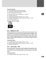
Connecting conditions
■
■
Connectable conductor cross-sections: 0.75 mm
2
…4 mm
2
■
■
Maximum cable length: 50 m
Note
The potential equalization set (PAS) may only be used with Compact Stations
for single tracking. Contact the SolarMax Service Center if you want to con-
nect the potential equalization set.
5.5.6 Grid connections
The MCU provides two RS485 interfaces (X621 / X821) and an Ethernet interface (X601)
for data communications. This can be used to link the Compact Station into a network,
which makes it possible to use the comprehensive monitoring and remote control options
(see Section 14).
Connecting conditions
■
■
RJ45 connector
■
■
Use CAT 5 cables
■
■
Permissible cable diameters in the small cable pass-through: 8 …18 mm
5.6
Wiring the inverter interfaces
The inverters of the Compact Station have interfaces for the ModularBus, hard emergency
shutdown and for checking the grid monitoring. Connecting the inverter(s) requires ope-
ning the unit(s) up; it is therefore necessary to power down the Compact Station before
starting with the connection work.
5.6.1 Cable installation
The cables are installed in the inverter and in the hollow base of the Compact Station.
The cables are threaded through the small cable pass-through in the connection area of
the Compact Station (see Section 3.4). The cables must have been laid out and attached
both inside and outside the Compact Station. Then the cable pass-through must be fitted

