en
37
as described in Section 5.1.
5.6.2 Connecting the master station with the slave station
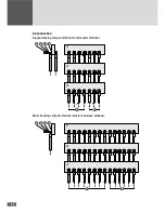
The communication between the master station and the slave station takes place via
ModularBus. The connecting cable is installed from the back of the slave station to the
front of the master station via the conduit and the M40 cable gland.
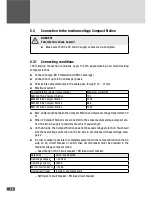
5.6.2.1 Connecting conditions
■
■
The Compact Station is powered down (see Section 9).
■
■
The connection may only be carried out by a specially instructed fitter.
■
■
Use CAT 6 S/FTP cable, length: 5 meters (the slave station is supplied with conduit
and with the communication cable connected).
■
■
Connect the cable at the PU 4 power unit in the master station (inverter WR2) (see
Section 3.8).
5.6.2.2 Procedure
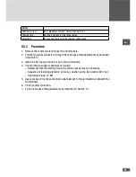
1. In order to gain access to the PU 4 power unit, remove the 2 side panels and the rear
panel as described in Section 5.2.3.
2. Remove the front cover of the WR2 inverter.
3. Attach the conduit to the M40 cable glands.
4. Pull the cable through the conduit into the master station.
5. Pull the cable into the inverter. The panel on the right-hand side has a cable pass-
through at the top (with cable grommet).
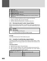
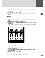
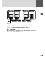
6. Connection at the PU 4 power unit in the master station:
– Remove the terminating plug (A) from the RJ45 or X632 socket.
– Connect the cable (B) where you have removed the terminating plug.
(A)
(B)
7. Re-close the inverter.
8. Fit the panels back on the Compact Station.

