38
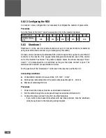
5.6.2.3 Configuring the MCU
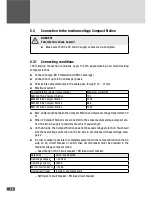
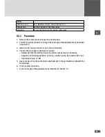
In a master / slave configuration it is necessary to configure the number of power units.
Procedure
Turn the "Num of LTs S241" switch (see section 5.5) to the required position:
Switch position
0
1
2
3
4
5
6
7
8
9
A
B
C
D
E
F
Number of power
units
N/A
3
N/A
6
N/A
9
N/A
12
N/A
5.6.3 Shutdown 1
Shutdown 1 can be used for remote shutdown of up to 4 Compact Stations (8 inverters)
using an external break contact (e.g. an emergency off switch).
A break contact connected to terminals SD1 and SD2 opens the supply circuit of the AC
contactor in the inverter. This causes immediate grid disconnection even if the control
unit of the inverter has failed. The graphics display shows the status message "Shut-
down 1". Grid disconnection is maintained as long as the break contact is open. The
terminals SD1 and SD2 are overridden ex factory.
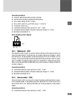
For the position of the "Shutdown 1" terminals in the inverter: see Section 3.7.
Connecting conditions
■
■
Connectable conductor cross-sections: 0.75 mm
2
…4 mm
2
■
■
Permissible cable diameters in the small cable pass-through: 8 …18 mm
■
■
Maximum cable length: 50 m
Procedure
1. Power down the Compact Station as described in Section 9.
2. Pull the cable through the cable pass through as described in Section 5.1.
3. Connect the break contact to the SC1 and SD2 terminals.
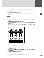
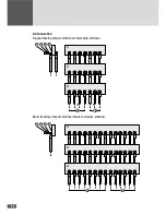
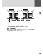
– If you want to block several inverters with one break contact, wire the shutdown
contacts as shown in the following wiring diagram.

