en
65
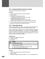
terminal block by releasing the slotted screws.
– [for power unit LT2: terminal block "LT2"],
– [for power unit LT3: terminal block "LT3"].
4. Slide all 4 slide switches downwards and secure the slide switches by tightening the
slotted screws.
5. Connect the three-phase alternating current generator to the V L1, V L2 and V L3 test
contacts at the "LT1" terminal block
– [for power unit LT2: terminal block "LT2"]
– [for power unit LT3: terminal block "LT3"]
– Use the lower 4 mm sockets on the test contacts.
– Connect the generator phases for clockwise rotation.
6. Connect the DC voltmeter to measure the control voltage of the AC contactor at the
upper and lower test contact K1EN.
7. Check the wiring in accordance with the wiring diagram below:

