background image

en

67


– The other DC circuit breakers and all AC circuit breakers in the Compact Station 

remain switched off.

9.  Switch on the AC generator.


– The external conductor voltages must correspond to the nominal mains voltage 

and frequency (3 x 280 V

AC

 / 50 Hz).

10.  Switch on the main switch. 


– The inverter starts and, after about 30 seconds, switches to (simulated) mains 

operation.

11.  Check that the control voltage of the AC contactor is 24 V

DC

.

12.  Now increase the voltage or the frequency of any one phase to just under the set limit 

(for limit values, see Section 13).

ATTENTION!
Possible damage to the inverter!

Never set the test voltage to a value higher than 364V (130% of the 
nominal voltage). The measuring circuits of the inverter may become 
damaged.

13.  Slowly increase the phase voltage or the frequency beyond the limit.
14.  Check that the grid monitoring function of the inverter reacts appropriately: the mea-

sured control voltage of the AC contactor must drop to 0 V.


– The test for power unit LT1 is complete when the control voltage of the AC con-

tactor drops.

15.  Switch off the main switch.
16.  Switch off the AC generator.
17.  Switch off the DC circuit breaker Q4.


– [power unit LT2: DC circuit breaker Q5]


– [power unit LT3: DC circuit breaker Q6]


– all DC circuit breakers are switched off

18.  Remove the AC generator and the DC voltmeter from the inverter.
19.  Slide the 4 slide switches of the test contacts back into the upper position and screw 

them down firmly.

20.  If required, repeat the test for power units LT2 and LT3: in each case start with step 

3 of these instructions. Follow the instructions in the square brackets.

21.  Remove all tools from the inverter.
22. Attach the covers and close the inverter.
23. Switch on the Compact Station as described in Section 6.1.

Summary of Contents for 330TS-SV Compact Station

Page 1: ...Instruction manual SolarMax TS SV 330TS SV Compact Station 360TS SV Compact Station 660TS SV Compact Station 720TS SV Compact Station...

Page 2: ...SolarMax Produktions GmbH Zur Sch nhalde 10 D 89352 Ellzee E Mail info solarmax com SolarMax Produktions GmbH 2015 2 2...

Page 3: ...en 3 en 3...

Page 4: ...Transporting and storing the Compact Station 17 4 2 Checking the delivery 18 4 3 Selecting the installation location 18 4 4 Installing the Compact Station 19 5 Electrical connection 21 5 1 Installing...

Page 5: ...ring the status signaling contact 41 6 3 4 Configuration of the PV generator monitoring 41 6 4 Displaying the configuration 43 6 5 Displaying the measured values 45 6 6 Displaying device data 47 7 Ope...

Page 6: ...10 1 2 Cleaning the ventilation grille 61 10 2 Maintenance with the inverters open 61 10 2 1 Checking the AC DC terminals in the inverters 62 10 2 2 Testing grid monitoring 62 11 Disposal 66 12 Speci...

Page 7: ...0TS SV Compact Station slave station multi tracking 1000 5386 SM360TS SV Compact Station slave station multi tracking 1000 5450 SM360TS SV Compact Station master station multi tracking 1000 5533 SM720...

Page 8: ...safety instructions and general information are used within this instruction manual DANGER Non observance of these safety instructions may immediately cause serious injuries or death WARNING Non obser...

Page 9: ...V modules into alternating current which conforms to the parameters of the public grid Any other use is contrary to the design purpose SolarMax Produktions GmbH accepts no liability for damage resulti...

Page 10: ...ins phase In this area it is not permitted to lift the Compact Station with a forklift truck This could damage the Compact Station In this area lifting with a forklift truck is not permitted Lifting p...

Page 11: ...ilable as an option for single tracking compact stations Over current protection The AC and DC circuit breakers of the inverters are equipped with thermo magnetic overcurrent triggers Temperature limi...

Page 12: ...12 3 3 Dimensions Vorderansicht linke Seitenansicht Draufsicht Schnitt A A...

Page 13: ...2 4 6 6 7 8 1 5 9 10 No Description 1 Self supply transformer available as an option 2 Fuse box 3 MCU Master Control Unit 4 AC connection 5 DC connection NH fuse circuit breaker 6 2 x ground terminals...

Page 14: ...y transformer available as an option 2 Fuse box 3 MCU Master Control Unit 4 AC connection 5 2 x ground terminals 6 System cable pass through elements for DC and AC connection 7 System cable pass throu...

Page 15: ...tion of the MaxWeb xp NX data logger and the potential equalization set PAS OFF ON 1 2 No Description 1 Graphics display see Section 7 1 2 Main switch Function of the main switch When the main switch...

Page 16: ...vable and provide access to the inverters 1 3 2 No Description 1 Upper side panel removable weight 26 kg fixing 6 x M8 hexagon socket screws 2 Lower side panel with air inlet grille removable weight 4...

Page 17: ...d connections at the inverter During normal operation the inverters run automatically 1 6 7 5 4 3 2 No Description 1 AC circuit breaker 2 Inverter type plate 3 DC connection only used with multi track...

Page 18: ...hown in the following diagram The measured values of the power units can be retrieved see Section 6 5 PU 1 PU 2 PU 3 PU 4 PU 5 PU 6 WR 1 WR 2 No Description WR 1 Inverter 1 PU 1 to PU 3 PU1 Power unit...

Page 19: ...rt and lifting devices have sufficient loading lif ting capacity The Compact Station must be transported in an upright position Caution establish the center of gravity The center of gravity of the Com...

Page 20: ...ymbol on the side of the Compact Station and Section 2 2 Maintain an unobstructed area of 1 meter around the Compact Station for mainte nance work The floor must be sufficiently load bearing and smoot...

Page 21: ...0 6 m s With Kf value 10 6 m s drainage must be provided with a connection to a water course without back pressure or open discharge No Description 1 Crushed stone 0 45 or sim max 5 fines content 2 Ex...

Page 22: ...22 Installation plan Compact Station 1000 mm Ev 2 50 MN m2 Ev 2 20 MN m2 725 400 75 1 4 3 2 5 7 6...

Page 23: ...ble pass through elements do not include a cable strain relief facility Cable strain relief is achieved using the perforated or C rails within the Compact Station Description 1 2 3 4 No Description 1...

Page 24: ...5 Slide the shrink sleeves on to the cables 6 Pull the clean cables through the cable pass through element and further to the con nection points 7 Connect the cables as described in Sections 5 2 5 3 5...

Page 25: ...hout folds and the hotmelt adhesive comes out all round 13 Let the cable pass through element cool down for 30 minutes do not disturb this process 14 Close any unused cover spigots with blank plugs VS...

Page 26: ...DC conductors can be connected Maximum DC input current 160 A per DC input The DC input at the extreme right No 6 must not be used Conductor cross sections min 95 mm2 max 240 mm2 Cable diameters that...

Page 27: ...en 27 25 mm M12 3 2 4 6 1 5 No Description 1 NH fuse circuit breaker...

Page 28: ...ed with M8 hexagon socket screws CAUTION Risk of injury The panels weigh over 25 kg each At least 2 persons are required for lifting the panels Procedure First remove the top side panel then the botto...

Page 29: ...erters 4 Pull the DC supply conductors through the cable pass through elements as described in Section 5 1 5 Install the DC supply conductors in the Compact Station to the DC terminals in the inverter...

Page 30: ...th between the Compact Station and medium voltage transformer 30 m When 2 Compact Stations are connected to the same medium voltage compact sta tion the two AC supply conductors must be of equal lengt...

Page 31: ...ough elements as described in Section 5 1 3 Install the AC supply conductors up to the AC terminals 4 Connect the AC supply conductors as follows Remember that the rotating field of the mains phases m...

Page 32: ...32 AC connection Single tracking compact stations only master stations L1 L2 L3 4 3 2 1 6 5 Multi tracking compact stations master and slave stations L1 L2 L3 4 3 2 1 6 5...

Page 33: ...g the Compact Station The ground connection of the Compact Station is achieved using a copper ring inserted into the ground as shown in the following diagram WR 1 WR 2 1 2 No Description 1 Copper cabl...

Page 34: ...Rotary switch S241 Num of LTs number of power units 6 RJ45 Ethernet socket 7 RJ45 RS485 socket 5 5 1 Cable installation The cable is installed in the cable duct beneath the MCU and through the small...

Page 35: ...cted via the voltage supply to the AC contactors but via software The Compact Station remains blocked until the external break contact is closed again In addition the graphics display shows the Shutdo...

Page 36: ...n into a network which makes it possible to use the comprehensive monitoring and remote control options see Section 14 Connecting conditions RJ45 connector Use CAT 5 cables Permissible cable diameters...

Page 37: ...cation cable connected Connect the cable at the PU 4 power unit in the master station inverter WR2 see Section 3 8 5 6 2 2 Procedure 1 In order to gain access to the PU 4 power unit remove the 2 side...

Page 38: ...n even if the control unit of the inverter has failed The graphics display shows the status message Shut down 1 Grid disconnection is maintained as long as the break contact is open The terminals SD1...

Page 39: ...ion 4 Break contact 4 Fit the front covers to the inverters and side panels to the Compact Station 5 Fit the cable pass through elements as described in Section 5 1 5 6 4 Test contacts The test contac...

Page 40: ...circuit breakers of the inverters 6 Switch ON the main switch at the MCU master station After a couple of seconds the status message Startup will be displayed Wait for the Mains operation status mess...

Page 41: ...ss to confirm your entry 3 Check your entries in the Validation menu You can then complete initial start up by pressing The main menu will then be displayed see Section 7 4 6 3 Settings Different comm...

Page 42: ...played by the inverter 6 3 2 Configuring the network parameters Device address A device address must be assigned to the inverter in order to communicate via RS485 interface or Ethernet Within the MaxC...

Page 43: ...Station starts grid operation the status signaling contact of the MCU will close immediately and remains closed for as long as the Compact Station is feeding in After the unit disconnects from the ma...

Page 44: ...eter 2 Make the required setting Setting Description Off The DC insulation monitoring is switched off Note Switching off the DC insulation monitoring is only necessary when using the equipotential bon...

Page 45: ...be displayed in the Configuration menu of the graphics display The configuration depends on the selected country setting In the Main menu select the Configuration menu back to the main menu scroll pa...

Page 46: ...imum increase of the effective power during grid recon nection upon previous failure related grid disconnection minute Soft Start Maximum increase of the active power at grid connection Unlike Pac pro...

Page 47: ...dually adjust the operating parameters The required SolarMax TS series parameter configu ration using MaxTalk 2 Pro operating manual can be downloaded from our website www solarmax com Downloads area...

Page 48: ...red value Description Unit Vdc DC input voltage V Pdc Input power kW Temperature Maximum temperature C Fan Operating condition of fans on off Status Operating status of the power unit on off error Not...

Page 49: ...menu select the Information menu back to main menu scroll display Display Description Commissioning Date of initial start up Serial no Serial number Device type Inverter type Operating hours Total op...

Page 50: ...the inverter 1 3 5 4 2 No Description 1 Graphic display with backlight 2 Status LED operating status display see section 7 6 3 Function keys membrane keypad 4 Display for Ethernet connection link disp...

Page 51: ...formation Measured values Language Time Date Device adress Ethernet IP System Power unit 1 Power unit 2 Power unit 3 Power unit 12 Days Month Years Total Reset Netmask TCP Port Status relais Status re...

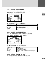
Page 52: ...ly yield kWh Total Total yield since commissioning kWh Status Current operating status of Compact Station see Section 7 6 7 4 Main menu You can open all menus from the Main menu see Section 7 2 In ord...

Page 53: ...s in the operating status Mains operation 7 5 2 Displaying the monthly statistics The monthly statistics show the statistics values for the selected month In the Statistics menu select the Month sub m...

Page 54: ...7 5 4 Displaying the total statistics The total statistics shows the statistics values since commissioning In the Statistics menu select the Total sub menu back to the Statistics menu Statistical val...

Page 55: ...losses are possible Warnings are independent of the operating status and are displayed on the graphics display alternately with the current status message Status LED Operating status Description Off T...

Page 56: ...en over sized or in the event of high irradiation Idc limitation The Compact Station limits the DC input current to the maximum permissible value This can occur where the design of the PV generator al...

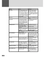
Page 57: ...describe the status messages in the event of failures the causes of the aforementioned and the possible measures 8 2 1 General troubleshooting Problem Cause Measures The display remains blank The MCU...

Page 58: ...rent in the PV generator Seal the generator connection box better and improve the insulation materials Note Check the setting of the functions of the Vsym monitor or Vsym AC monitor Power unit blocked...

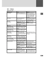
Page 59: ...ency too low Frequency too low BP The mains frequency is outside the f min 1 or f min 2 limit values Vac too high Vac too high BP The mains voltage at the specified phase is outside the Vac max 1 or V...

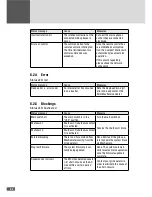
Page 60: ...git error code and contact the SolarMax Service Center 8 2 5 Blockings Status LED flashes red Status message Cause Measure Main switch off The main switch is in the OFF position Turn the main switch o...

Page 61: ...initialization phase Status LED does not glow The following errors occur only during the inverters initialization phase Error Measure SUPPLY FAULT Contact the SolarMax Service Center ADC REFERENCE ER...

Page 62: ...atus message will be displayed 2 Remove the 4 side panels from the Compact Station master and or slave station as described in Section 5 2 3 3 Switch off all AC circuit breakers of the inverters maste...

Page 63: ...during cleaning Procedure 1 Fold down both air inlet flaps see Section 3 6 First remove the 4 x M8 screws at the side of the air inlet flap CAUTION Risk of injury Secure the air inlet flap against dr...

Page 64: ...with single tracking and multi tracking compact stations The test contacts permit a separation of the measuring lines between the respective power unit and the three phase voltages V L1 V L2 and V L3...

Page 65: ...e alternating current generator to the V L1 V L2 and V L3 test contacts at the LT1 terminal block for power unit LT2 terminal block LT2 for power unit LT3 terminal block LT3 Use the lower 4 mm sockets...

Page 66: ...K1EN K1 U L1 U L2 U L3 K1EN K1 2 1 LT 2 LT 3 No Description 1 4 mm sockets to control unit 2 4 mm sockets to the AC terminals 3 Sliding switches G AC generator V V DC voltmeter 8 Switch on the Q4 DC c...

Page 67: ...or the frequency beyond the limit 14 Check that the grid monitoring function of the inverter reacts appropriately the mea sured control voltage of the AC contactor must drop to 0 V The test for power...

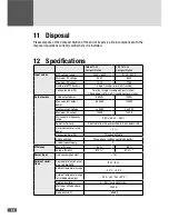
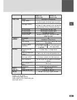
Page 68: ...kW Max apparent output power 684kVA 738kVA Nominal mains voltage 3 x 280V 3 x 320V Maximum AC current 1404A 1332A Mains nominal frequency range 50 Hz 45 Hz 55 Hz Power factor cos Adjustable from 0 8 o...

Page 69: ...ntry setting selected at the time of commissioning Standard guideline compliance G59 2 BDEW MV Guide line PPC Guide RD 661 Allegato A70 G59 2 BDEW MV Guideline PPC Guide RD 661 Interfaces Data communi...

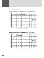
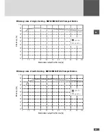
Page 70: ...92 90 88 86 84 82 80 0 10 20 30 40 50 60 70 80 90 100 450 VDC 550 VDC Standardised output Pac Pac max Efficiency Efficiency curve of multi tracking SM660 SM330TS SV Compact Station 100 98 96 94 92 90...

Page 71: ...86 84 82 80 0 10 20 30 40 50 60 70 80 90 100 510 VDC 600 VDC Standardised output Pac Pac max Efficiency Efficiency curve of multi tracking SM720 SM360TS SV Compact Station 100 98 96 94 92 90 88 86 84...

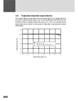
Page 72: ...or 43 C depending on the filter used in the ventilation grilles At ambient temperatures above 40 C or 43 C it is possible that the yield of the device is reduced For this reason is it imperative to a...

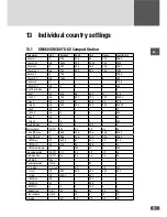
Page 73: ...f max 1 ms 100 200 200 200 90000 f min 2 Hz 47 t f min 2 ms 0 0 0 0 500 f max 2 Hz 52 t f max 2 ms 0 0 0 0 500 Restart delay s 0 0 300 0 0 Mains check On Off On On Off On On Vac MC max V 364 308 308...

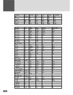
Page 74: ...min max V f min 1 Hz 49 5 59 3 47 59 3 t f min 1 ms 600500 2000 500 2000 f max 1 Hz 50 2 60 5 52 60 5 t f max 1 ms 120500 160 500 160 f min 2 Hz 48 57 57 t f min 2 ms 200 160 0 160 f max 2 Hz 50 5 t f...

Page 75: ...00 Vac max 2 V 358 4 t Vac max 2 ms 0 0 0 0 500 Vac 10 min max V f min 1 Hz 47 5 48 45 5 47 47 5 t f min 1 ms 100 200 200 200 20000 f max 1 Hz 51 5 51 54 5 52 51 5 t f max 1 ms 100 200 200 200 90000 f...

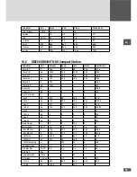
Page 76: ...2000 1000 200 1000 Vac min 2 V 160 160 160 t Vac min 2 ms 100 160 0 160 Vac max 2 V 384 384 t Vac max 2 ms 0 160 0 160 Vac 10 min max V f min 1 Hz 49 5 59 3 47 59 3 t f min 1 ms 600500 2000 500 2000...

Page 77: ...2 60 2 f stop Hz 60 05 60 05 f MC max Hz f MC min Hz MC time s 0 0 0 0 Reduction Hz 40 40 40 40 Re increase min 10 10 Q mode Off Off Off Off FRT On Off On Off Off Off K factor 0 0 0 0 0 0 0 0 S max kV...

Page 78: ...gger for recording measured values yield data and events MaxWeb NX pro The solar plant controller MaxWeb NX pro allows for controlling the active and reactive powers of the PV plant directly at the gr...

Page 79: ...ery of the device by SOLARMAX Central Inverters Series C S TS TS SV 24 months from purchase date but max 30 months after delivery of device by SOLARMAX Series RX 60 months from purchase date but max 6...

Page 80: ...ble at a reasonable expense SOLARMAX is authorized to replace the defect device In this case the above mentioned terms of replacement are applicable 3 Duration of Guarantee for Device Repair Device Re...

Page 81: ...eries Number of Product In case of a replacement this certificate will not be adjusted to the new series number In this way the guarantee extension stays unaffected a Time Limit for entry into Guarant...

Page 82: ...n shall exclusively be Augsburg Germany as far as this is permitted by law Appendix Country List Austria Belgium Bulgaria Czech Republic Denmark France Germany Greece Italy Liechsten stein Luxembourg...

Page 83: ...en 83 Notes...

Page 84: ...ur website for contact details www solarmax com en services warranty www solarmaxservice com Hotline DE 49 3733 507840 CH 41 315281165 ES 34 93 2203859 GB 44 20 38080346 IT 39 0418520076 FR 33 820 420...

Reviews: