24
WARNING!
Risk of death by fire!
■
■
Provide separate fuses for each inverter.
■
■
Do not attach any loads between inverter and fuse.
■
■
If you use external residual current devices (RCDs), use the type A or B RCDs with a
nominal leakage current of at least 100 mA. For PV plants with large leakage current
capacities, the RCDs to be used should have a nominal leakage current capacity of at
least 300 mA.
Procedure
1. Remove the cover of the inverter as described in Section 5.1.1.
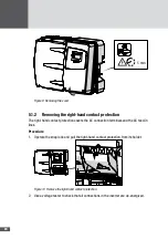
2. Remove the right-hand contact protection as described in Section 5.1.2.
3. Thread the AC feed cable through the right-hand cable gland.
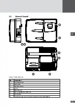
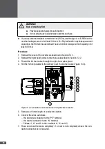
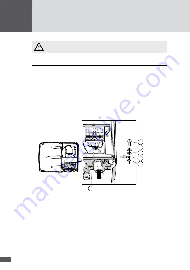
4. Pull the ferrite (included in the delivery) over the AC feed cable (Figure 13/0).
5
4
3
2
1
0
Figure 13 AC connection and connection for 2nd protective conductor
5. Remove an 18 mm length of conductor isolation.
6. Connect the wires as follows:
– the protective conductor to the "PE" terminal
– the neutral conductor to the "N" terminal
– Phases L1, L2 and L3 to the terminals L1, L2 and L3
7. Press and close the levers completely. If a lever is not completely closed, the con-
ductor connection is not secured.

