en
33
Procedure
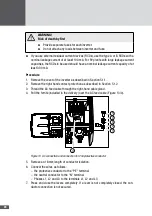
1. Remove the cover of the inverter as described in Section 5.1.1.
2. Remove the left-hand contact protection as described in Section 5.1.3.
WARNING!
Fatal electric shock hazard!
Cables conducting mains voltage must be covered by the contact protection
inside the inverter.
■
■
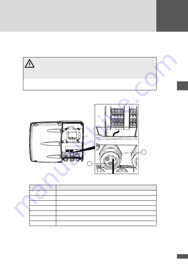
Route the connection cable through the left-hand cable gland
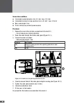
(Figure 23 / 1).
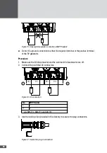
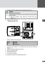
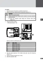
3. Connect the wires as follows:
– Wire stripping length: 7 mm
1
2
Figure 23 Connection of external power control
Contact
Description
K1
Control signal relay K1
K2
Control signal relay K2
K3
Control signal relay K3
K4
Control signal relay K4
K5
Control signal relay K5
K6
Control signal relay K6
N
Neutral conductor
4. Close the unused apertures in the multiple cable gland using the locking pins
(Figure 23 / 2).
5. Tighten the cable gland (wrench size: 34 mm).
6. Check the cable strain relief.

