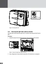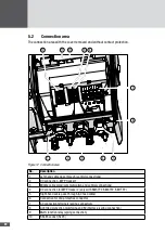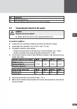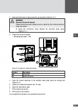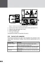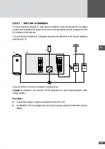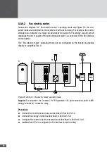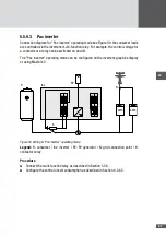
34
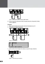
7. Fit the contact protection.
8. Fit the cover of the inverter.
You can switch the inverter on as described in Section 6.1.
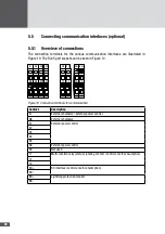
556 Multi-function relay
The multi-function relay can be used as status signaling contact for the remote control of
the inverter (see section 6.3.4) or for the control of self-consumption (see section 5.5.9).
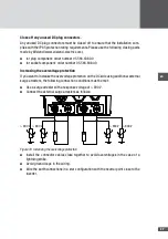
11
12
14
NC
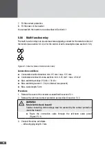
Figure 24 Contact scheme of multi-function relay
Connection conditions
■
■
Connectable cable diameters: min. 9.5 mm / max. 12.5 mm
■
■
Connectable conductor cross-sections: min. 0.25 mm
2
/ max. 2.5 mm
2
■
■
Max. switching voltage: 250 V
AC
/ 30 V
DC
■
■
Max. switching current: 1.5 A (no internal fuse present)
■
■
Max. cable length: 50 m
Procedure
1. Remove the cover of the inverter as described in section 5.1.1.
2. Remove the left-hand contact protection as described in section 5.1.3.
WARNING!
Fatal electric shock hazard!
Cables conducting mains voltage must be covered by the contact protection
inside the inverter.
■
■
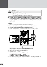
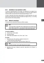
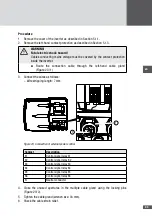
Route the connection cable through the left-hand cable gland
(Figure 25 / 1).
3. Connect the wires as follows.
– Wire stripping length: 7 mm

