36
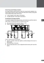
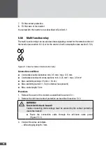
Connection conditions
■
■
Connectable cable diameters: min. 9.5 mm / max. 12.5 mm
■
■
Connectable conductor cross-sections: min. 0.25 mm
2
/ max. 2.5 mm
2
■
■
Max. cable length: 50 m
■
■
Do not connect any external power sources.
Procedure
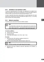
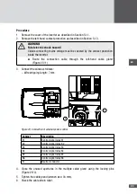
1. Remove the cover of the inverter as described in Section 5.1.1.
– Do not remove any contact protection.
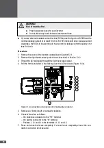
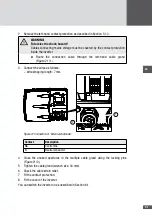
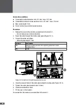
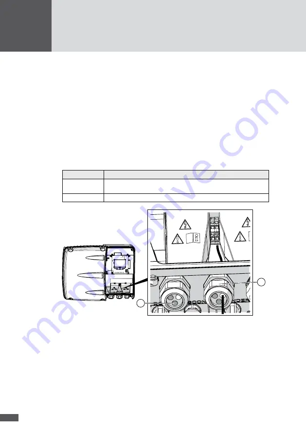
2. Route the cable through the middle cable gland (Figure 26 / 1).
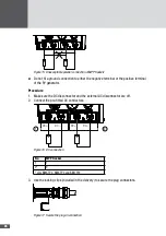
3. Connect the wires as follows:
– Wire stripping length: 7 mm
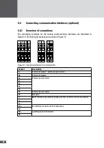
Contact
Description
BS+
Remote signaling contact of the lightning protection module
(potential-free)
BS–
COM
1
2
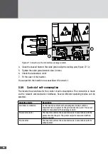
Figure 26 Connection of the lightning protection module
4. Close the unused holes in the cable gland using the locking pins (Figure 26 / 2).
5. Tighten the cable gland (wrench size: 34 mm).
6. Check the cable strain relief.
7. Fit the cover of the inverter.
You can switch the inverter on as described in Section 6.1.

