en
25
C
B
A
18 mm
Abbildungen Klemme: Phoenix Contact
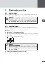
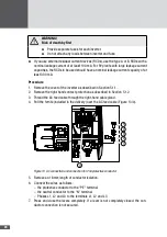
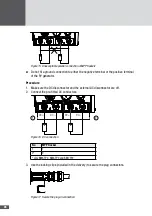
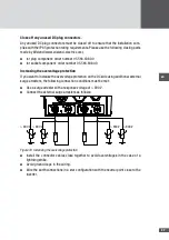
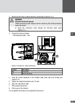
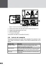
Figure 14 Connect the AC terminals.
8. Check the cable connections for firm seating.
9. Tighten the cable gland (wrench size: 34 mm).
10. Check the cable strain relief.
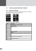
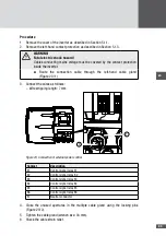
11. Connect the second protective conductor (see Figure 13).
– Assembly sequence: toothed lock washer M5 (1), lug (2), washer M5 (3), spring
washer M5 (4), Phillips head screw M5 x 12 (5)
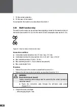
12. Fit the contact protection.
13. Fit the cover of the inverter.
54
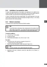
Connecting the inverter to the PV generator
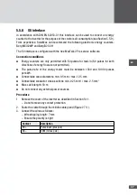
The inverters of the TP series are operated in dual tracking mode. In the dual tracking
mode a separate MPP tracker is available for each DC input.
Connection conditions
■
■
Connection of maximum 2 strings (1 string in the case of SM4TP)
DANGER!
Risk of death by fire!
High return currents can cause a fire risk for the PV generator.
■
■
When Y plugs are used in order to connect more than 2 strings (more than
1 string in the case of SM4TP), each DC feed cable must be protected
individually against dangerous return currents.
■
■
Maximum DC input current: 10 A per DC input
■
■
Maximum DC input voltage: 900 V
■
■
Select the conductor cross-section to suit the system configuration.
■
■
Exclusively use Wieland PST40i1C connectors (the mating connectors are not
included in the package supplied)
■
■
Parallel connection of the MPP trackers is not permitted:

