en
29
552 Installation of communication cables
To ensure the operational safety of the inverter, the cables have to be installed in the
inverter as described in this section of the instructions. The left-hand contact protection
covers the cables and connections with dangerously high voltages (> 50 V).
In order to ensure that the inverter remains sealed, the unused apertures in the cable
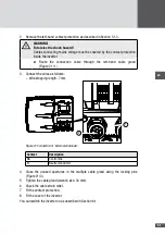
glands must be closed with the locking pins (example see Figure 20 / Pos. 2). The locking
pins are included in the delivery package.
553 Network connections
The inverter can be connected to Ethernet and RS485 networks.
Note
You will find further details about data communication in the technical infor-
mation "MaxComm network". You can download this document from our web-
site at: www.solarmax.com; Downloads/Data Communication/MaxComm.
Connection conditions
■
■
Connection type: RJ45 sockets
■
■
Use shielded cables.
■
■
Connectable cable diameters: min. 5.5 mm / max. 7.0 mm
Procedure
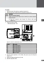
1. Remove the cover of the inverter as described in Section 5.1.1.
– Do not remove any contact protection.
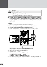
2. Route the grid cable through the middle cable gland ( Figure 20 / 1).
Note
The RJ45 connectors can be pulled through the cable gland.
3. Depending on the type of network, connect the cable either to the "Ethernet" or
"RS485" socket.


