30
1
2
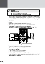
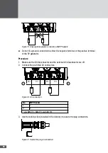
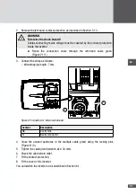
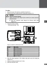
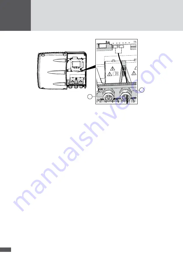
Figure 20 Connecting the grid cables
4. Close the unused apertures in the multiple cable gland using the locking pins
(Figure 20/2).
5. Tighten the multiple cable gland (wrench size: 34 mm).
6. Check the cable strain relief.
7. Fit the cover of the inverter.
554 External shutdown
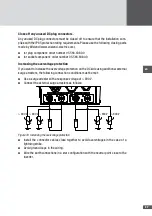
This interface can be used to connect the inverter to an external grid monitoring system
which disconnects the inverter from the mains grid when this is needed.
While the external grid monitoring signal (the phase voltage) is active at the "NA" contact,
the inverter feeds into the grid. When the signal stops, the grid relays K1 and K2 of the
inverter are opened (see Figure 3). This immediately disconnects the inverter from the
grid.
The interface can only be configured with the free MaxTalk 2 Pro service software (see
Section 12).
Connection conditions
■
■
Connectable cable diameters: min. 9.5 mm / max. 12.5 mm
■
■
Connectable conductor cross-sections: min. 0.25 mm
2
/ max. 2.5 mm
2
■
■
Max. input current: 25 mA
■
■
Max. input voltage: 230 V
AC
Procedure
1. Remove the cover of the inverter as described in Section 5.1.1.

