en
35
1
2
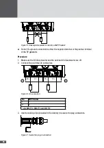
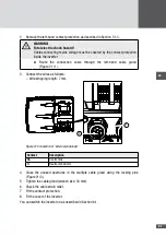
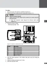
Figure 25 Connection of multi-function relay
Contact
Description
11
COM
12
Opener (when used as status signaling contact: opener in the case of error)
14
Closer (when used as status signaling contact: closer in the case of error)
NC
Not used
4. Close the unused apertures in the multiple cable gland using the locking pins
(Figure 25/2).
5. Tighten the middle cable gland (wrench size: 34 mm).
6. Check the cable strain relief.
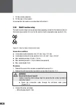
7. Fit the contact protection.
8. Fit the cover of the inverter.
You can switch the inverter on as described in Section 6.1.
557 Lightning protection monitor
This interface can be used for monitoring an external lightning protection module. The
configuration is done using the inverter's graphics display (see Section 6.3.5) or with
MaxTalk 2.
When the remote signaling contact of the lighting protection module connected to the
input closes, the inverter displays the corresponding status message/warning on the
graphics display. It is possible to connect multiple lightning protection modules in parallel
to the lightning protection input.


