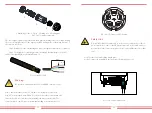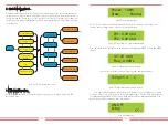
Pic 5.7 AC connector structure
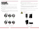
The AC output connector is divided into three parts: matching ocket, sleeve sand sealing
sleeve, as shown in Picture 5.7, the steps are as fand sealing sleeve, as shown in Picture 5.7,
the steps are as follows:
Step 1 Remove the cable sealing ring and sleeve in sequence from the AC connector.
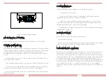
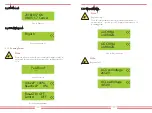
Step 2 Use strippers to strip the protective sheath and insulation layer of the AC
cable to the right length, as shown in Picture 5.8.
Pic 5.8 Strip AC cable
War
ning:
Be careful to distinguish the L1, L2,L3 and PE of the AC cables.
8~15mm
40mm
1. Matching socket 2.Sleeve 3.Sealing core 4.Sealing nut
1
2
3
4
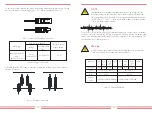
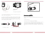
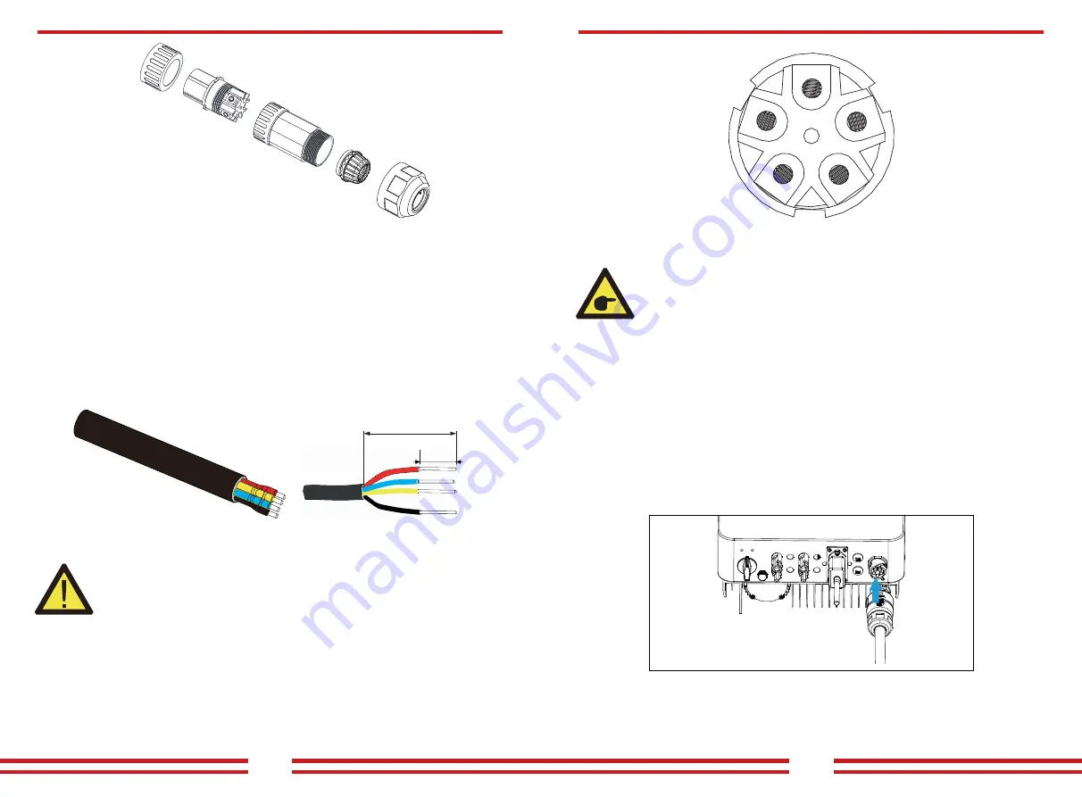
Pic 5.10 AC input connection
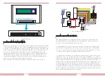
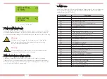
Pic 5.9 AC Connector Hole Pattern
Step 3: Insert the cable (L1, L2, L3, PE) into the sealing sleeve and sleeve.
Step 4 Use the hexagon screwdriver, loosen the bolts of the socket in turn, and
insert each cable core into the corresponding jack, and set each screw. The
connection hole of AC connection terminal labeling is shown in Picture 5.9.
Step 5 Set the sleeve and sealing ring in place
Step 6 Connect the terminals to the inverter as shown in picture 5.10.
Safety Hint:
The AC cable line L1 is connected to socket 1; L2 is connected to socket 2;
L3 is connected to socket 3, the PE line is connected to the earth , and does
not involve N wire connections, please do not insert N lines into the socket
of N.
- 15 -
- 16 -


