- 21 -
- 22 -
When you are reading this, we believe that you have completed the connection according
to the requirements of chapter 5, if you has been running your inverter at this time, and
you want to use the limiter function, please turn off AC and DC switch of the inverter, and
wait for 5 minutes until the inverter completely discharged. In order to make it easier for
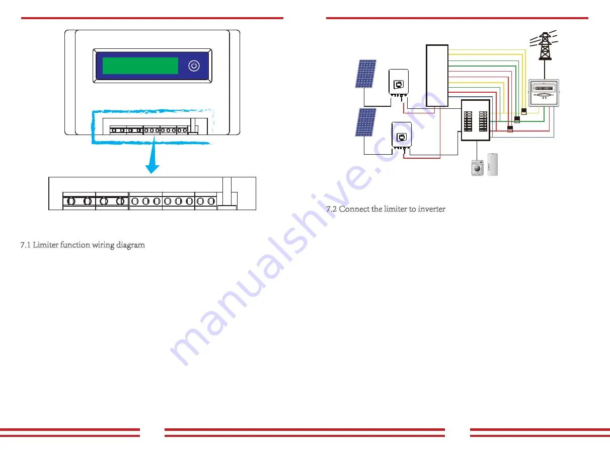
you to use the limiter function of the inverter, we have specifically given the wiring
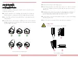
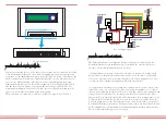
diagram,as shown in Picture7.2, the red lines connected to the utility grid called wire (L),
blue line shows the zero line(N), yellow green line shows the ground wire (PE). We
recommend installing an AC switch between the inverter outlet and the utility grid, the
specs of the AC switchis determined by the load capacity.
The AC switch we recommend to connect to the inverter output refer to Table 5.2.
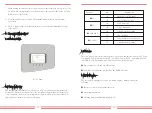
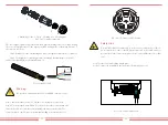
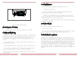
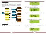
7.1 Limiter function wiring diagram
Pic 7.1 Limiter view
- 20 -
L1
L1(L)L1(K)L2(L)L2(K)L3(L)L3(K)
+ -
L2
L3
N
U
V
L1(L)
Solar panels
Load
Distribution Box
Limiter
Control signal
L1(K)
L2(L)
L2(K)
L3(L)
L3(K)
L1
L2
L3
N
W
N
Control signal
Pic 7.2 Wiring diagram
7.2 Connect the limiter to inverter
The limiter will measure the voltage and current of three phases separately, and this
manual only introduces the installation steps of one phase, the other two phases are
the same. The specific installation steps are as follows:
(1)Connect limiter to the grid. Connected to the grid is to measure the voltage of grid.
Before connect to the grid, please turn off the switch to avoid the risk of electric shock.
Choose one wire from the bottom of the three-phase DC switch. (any phase of U,V,W)
to connect with L1 terminal, then tighten the line with a screwdriver.
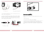
(2)Connect limiter to clamp senor. Clamp senor can measure the current of the AC side,
it should be connected to the front side of the load (domestic appliance ect.) to achieve
this function. Only when the limiter collects the voltage and current of the same phase can
it judge the power of the phase. So the clamp senor should be connected to the same
phase as the before. Open the side buckle of the clamp senor, then clamp the senor to the
AC line on the DC switch, the arrow direction on the senor should towards that of the
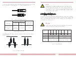
load. The clamp senor has two lines (shown as below), and the white line corresponds to
K terminal, black line corresponds to L terminal. Connect the white line to the L1(L) and
L1(K) terminal refer to the line mark of the limiter and tighten the line with screwdriver.
This is the whole installation process of one phase.

