- 23 -
- 24 -
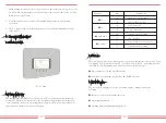
When the connection is completed, the following steps should be referenced to use this
function:
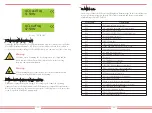
1.Turn on the AC switch
2. Turn on the DC switch , Waiting inverter LCD lighting up
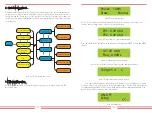
3.Press Enter button on the LCD panel in the main interface into the menu options, select
[parameter setting] to Enter setup submenu, and then select [running parameters] as
shown in figure 7.8,at this time please Input the default password 1234 through pressing
the button [up down, confirm], enter the operation parameter setting interface, Shown as
figure:
7.3 Use of anti-backflow function
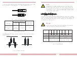
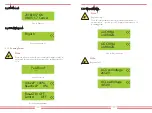
Pic7.5
Waterproof terminal
Pic7.6
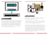
Connect limiter to inverter
1
2
limiter
+ -
1
2
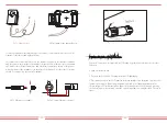
Pic7.3 Clamp Senor
Pic7.4
Clamp Senor internal arrow
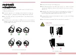
(3)After you finish the installation in process 1 and 2, connect the N line (N) to the N
terminal of the limiter and tighten the line.
(4)Connect the control line. There are two numbers 1 and 2 on the interface of limiter,
and the same on the waterproof terminal of the inverter. Twist the waterproof terminal
and connect the red line to number 1 and black line to number 2 shown as the picture.
After that connect the terminal to the interface of the limiter. The other side of the line
should be connected to the control terminal.
L
K

