3.2 Status Indicator
3. Operation Interface
3.1Interface View
8. Don't insert and remove AC and DC terminals when the inverter is in normal
operation.
9. The DC input voltage of the inverter must not exceed the maximum input voltage
of the model.
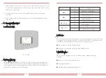
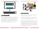
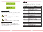
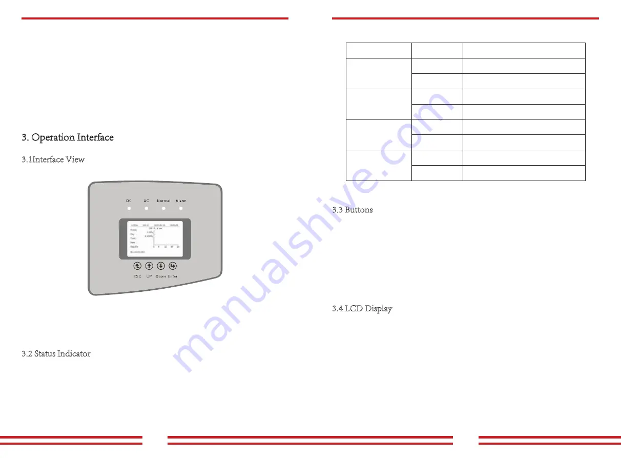
The inverter panel has 4 indicators, the left one is DC output indicator(green),indicates
normal DC input power status. Beside is the AC indicator(green),indicates normal AC
connecting status. Next is the operating in dicator(green) indicates normal output. The
right indicator is alarm(red), indicates alarming.
7. When starting the inverters, first close the circuit breaker at the grid side, then close the
DC side; when closing the inverters, first disconnect the circuit breaker at the AC side,
then disconnect the DC side.
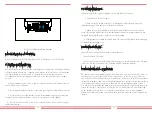
Pic 3.1 Panel
3.3 Buttons
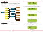
There are four buttons on the inverter panel:above is up and increase button (UP), below
is down and decrease button (DOWN), left is ESC button (ESC), right is Enter button
(ENTER). The following functions can be achieved by the four buttons:
● Page turning (use UP and DOWN button)
● Modify adjustable parameters (use ESC and ENTER button)
3.4 LCD Display
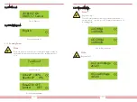
The three-phase string inverters use a dot matrix display,mainly contains the
following:
● Inverter operation status and information;
● Operating information;
● Warning message and malfunction display.
Explanation
Inverter detects DC input
Low DC input voltage
Grid Connected
Grid Unavailable
Under normal operating
Stop operating
Detected faults or report faults
Under normal operating
Indicator
status
●DC
●AC
● NORMAL
● ALARM
on
off
on
off
on
off
on
off
- 05 -
- 06 -

