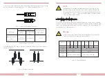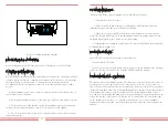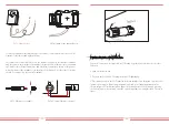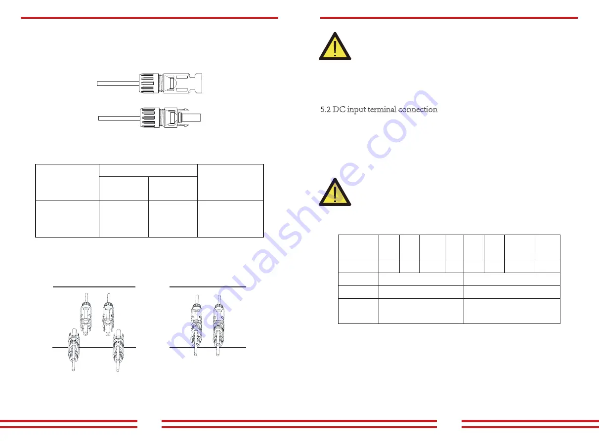
2). Insert the contact pin into the connector housing until it locks in place. Screw the cap
nut onto the connector housing. Torque to 2.5-3Nm(as shown in Picture 5.5)
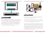
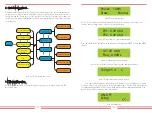
3).Finally insert the DC connector into the positive and negative input of the inverter,
shown as Picture 5.6
Pic 5.5 connector with cap nut screwed on
Sheet 5.1 Specs of AC cable
Pic 5.6 DC input connection
2
Traverse area(mm )
Cable type
Range
4.0(12AWG)
5.5-9.0
Recommended
size
Outside diameter
of cable(mm)
4.0-6.0
(12-10AWG)
Industry generic PV
cable
(model;PV1-F)
NOTE:
Sunlight shines on the panels will generate voltage, high voltage in series
may cause danger to life. Therefore, before connecting the DC input line,
the solar panel needs to be blocked by the opaque material and ensure that
the DC switch is ‘OFF’, otherwise, the high voltage of the inverter may
lead to life-threatening conditions.
Do not close the DC switch after the DC terminalis connected.Connect the AC terminal
to the AC size of the inverter, the AC size is equipped with Three-phase AC terminals that
can be conveniently connected.Flexible cords are recommended for easyinstallation. The
specifications are as shown in sheet 5.2.
War
ning:
Prohibit using a single circuit breaker for multiple inverters , prohibit the
connection of load between inverter circuit breakers.
Sheet 5.2 Cable information
5.2 DC input terminal connection
Outside cable(3+PE)20m Outside cable(3+PE)20m
Specification
Model
SM-5k/6K/7K/8K-G3P
16A/400V
SM-10K-G3P
25A/400V
Dia
Cable item
Cable
CSA
Cable
outer
dia
15~18mm
2.5mm 4mm
AWG
Dia
Cable
CSA
6mm
10
2.5mm
Cable
outer
dia
AWG
15~18mm
10
2
2
Breaker
Max cable
length
- 13 -
- 14 -

