28
1
2
3
4
A
GND
15 V
B
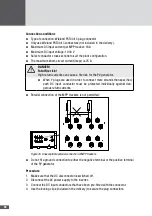
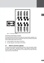
Figure 18 Network connections
No�
Description
1
RJ45 socket RS485
2
RS485 plug connection
B
Bus B
15 V
15 V network input
GND
Network input ground connection
A
Bus A
3
RJ45 socket RS485
4
RJ45 socket Ethernet
Note
You will find further details about data communication in the technical infor-
mation "MaxComm network". You can download this document from our web-
site at: www.solarmax.com; Downloads/Data Communication/MaxComm.
Connection conditions
■
■
Connection types: 3 x RJ45 sockets / 4-pole plug (included in the delivery)
■
■
Suitable conductor cross sections (plug connector): 0.25 to 2.5 mm
2
■
■
Multiple cable gland; usable cable
Ø
: 5.5 to 7.0 mm
■
■
You should use shielded network cables (cat. 5)
Procedure
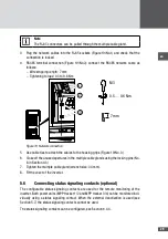
1. Remove the cover of the inverter as described in section 5.1.
2. Thread the network cables through the multiple cable gland.
Summary of Contents for SM30HT4
Page 1: ...Instruction manual SolarMax HT series 30HT4 32HT4...
Page 10: ...10 3 4 Dimensions mm 590 580 397 847 871 Figure 1 Dimensions with wall mounting bracket...
Page 11: ...en 11 3 5 Views of the unit 2 3 4 12 11 9 10 8 7 7 6 1 5 Figure 2 Views of the unit...
Page 74: ...SolarMax Service Center hotline solarmax com www solarmax com service 2014 05 en...

