en
29
Note
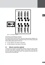
The RJ45 connectors can be pulled through the multiple cable gland.
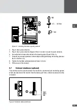
3. Plug the network cables into the RJ45 sockets (Figure 19/No.1) and check that the
connection is locked.
4. RS485 terminal connection (Figure 19/No.2): connect the RS485 network cable as
follows:
– Wire stripping length: 7 mm
– Tightening torque: 0.5 to 0.6 Nm
0.5 … 0.6 Nm
M3
7 mm
3
2
1
Figure 19 Network connection
5. Use cable ties to attach the cables to the housing grips (Figure 19/No. 3).
6. Close off the unused apertures in the multiple cable glands using the locking pins (No.
8 in Section 4.3).
7. Tighten the multiple cable gland (wrench size: 34 mm).
8. Fit the cover of the inverter.
5�6
Connecting status signaling contacts (optional)
The configurable status signaling contacts are used for the remote monitoring of the
inverter. Both power units (MPP tracker 1/2 and MPP tracker 3/4) can be monitored indi-
vidually using a status signaling contact. When the external deactivation is used (see
Section 5.7) the status signaling contacts cannot be used.
The status signaling contacts can be configured, see Section 6.4.4.
Summary of Contents for SM30HT4
Page 1: ...Instruction manual SolarMax HT series 30HT4 32HT4...
Page 10: ...10 3 4 Dimensions mm 590 580 397 847 871 Figure 1 Dimensions with wall mounting bracket...
Page 11: ...en 11 3 5 Views of the unit 2 3 4 12 11 9 10 8 7 7 6 1 5 Figure 2 Views of the unit...
Page 74: ...SolarMax Service Center hotline solarmax com www solarmax com service 2014 05 en...

