58
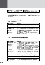
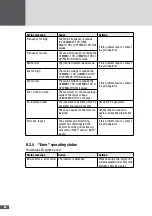
Status of LED
Operating status
Description
Flashes red
Blocked
Inverter is blocked
→
grid disconnection
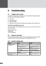
The "Failure", "Error", and "Blocked" operating status messages, as well as the warn-
ings, usually require certain actions to be carried out by the qualified electrician in charge
(see Section 8).
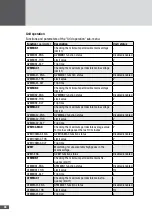
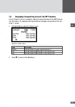
7�7�1 "Booting" operating status
Status LED: flashes green
Status message
Description
No response
The specified power unit (MPP tracker 1 / 2 or MPP tracker 3 / 4)
does not respond. The cause could be insufficient solar irradiation.
The inverter uses the available MPP tracker to feed into the grid.
Irradiation too low
The solar irradiation or rather the available output is too low for
mains operation.
Start-up…
The inverter checks the internal hardware and software compo-
nents before connecting to the mains.
Restart delay
The inverter delays connection to the grid (after a disconnection
from the grid or when booting).
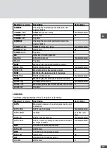
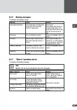
7�7�2 "Mains operation" operating status
The status LED lights up green.
Status message
Description
Maximum output power
The inverter limits the in-feed power to the maximum possible
value. This may occur if the PV generator is oversized.
Mains operation
The inverter is in feed mode.
Idc limitation
The inverter limits the PV generator current to the maximum per-
missible value. This may occur if the PV generator is designed such
that the current at the Maximum Power Point (MPP) exceeds the
maximum permissible input current of the inverter.
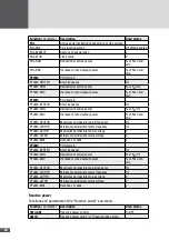
Iac limitation
The inverter limits the output power to the maximum permissible value
(where the PV generator is oversized).
Restart limitation
Following an external output limitation the inverter increases the
active power with defined progression (Pac progression and/or Soft
Start).
Frequency limitation
The inverter temporarily limits the active power owing to an active
frequency-dependent power reduction.
External limitation
The inverter's fed-in active power is limited by external output
control.
Temperature limitation
The output power is temporarily reduced in order to limit the
inverter's temperature.
Summary of Contents for SM30HT4
Page 1: ...Instruction manual SolarMax HT series 30HT4 32HT4...
Page 10: ...10 3 4 Dimensions mm 590 580 397 847 871 Figure 1 Dimensions with wall mounting bracket...
Page 11: ...en 11 3 5 Views of the unit 2 3 4 12 11 9 10 8 7 7 6 1 5 Figure 2 Views of the unit...
Page 74: ...SolarMax Service Center hotline solarmax com www solarmax com service 2014 05 en...

