en
21
5 Electrical connection
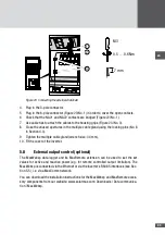
The DC terminals are freely accessible from the outside of the inverter. The AC terminals
and all communication terminals are inside the inverter.
The inverter may only be installed by qualified electricians.
5�1
Removing the cover
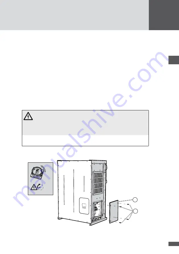
The AC and communication terminals are accessible when the cover is removed.
Procedure
1. Disconnect the AC power supply to the inverter.
2. Disconnect all control cables connected to the inverter (status relays, external grid
monitoring and shut-down).
3. Switch off the DC disconnector at the inverter.
DANGER!
Fatal electric shock hazard!
Components within the inverter are charged with a high voltage. After the
inverter has been disconnected, high residual voltages remain in the inverter
for approx. 5 minutes.
■
■
Wait 5 minutes until the voltages inside the inverter have reduced before
removing the cover and carrying out connection work.
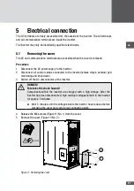
4. Release the M6 screws (Figure 11/No. 1) from the cover.
5. Remove the cover (Figure 11/No. 2).
5 min
O
1
2
Figure 11 Removing the cover
Summary of Contents for SM30HT4
Page 1: ...Instruction manual SolarMax HT series 30HT4 32HT4...
Page 10: ...10 3 4 Dimensions mm 590 580 397 847 871 Figure 1 Dimensions with wall mounting bracket...
Page 11: ...en 11 3 5 Views of the unit 2 3 4 12 11 9 10 8 7 7 6 1 5 Figure 2 Views of the unit...
Page 74: ...SolarMax Service Center hotline solarmax com www solarmax com service 2014 05 en...

